
In the highly regulated world of medical instrumentation, the difference between a prototype and a market-ready device often lies in the efficiency of the assembly process. Achieving superior yields requires moving beyond standard manufacturing—it demands a rigorous Design for Manufacturing (DFM) framework that anticipates assembly challenges before they reach the production floor. This guide provides a technical roadmap for optimizing your medical box builds to ensure precision, reliability, and regulatory compliance.
The Strategic Importance of Early-Stage DFM
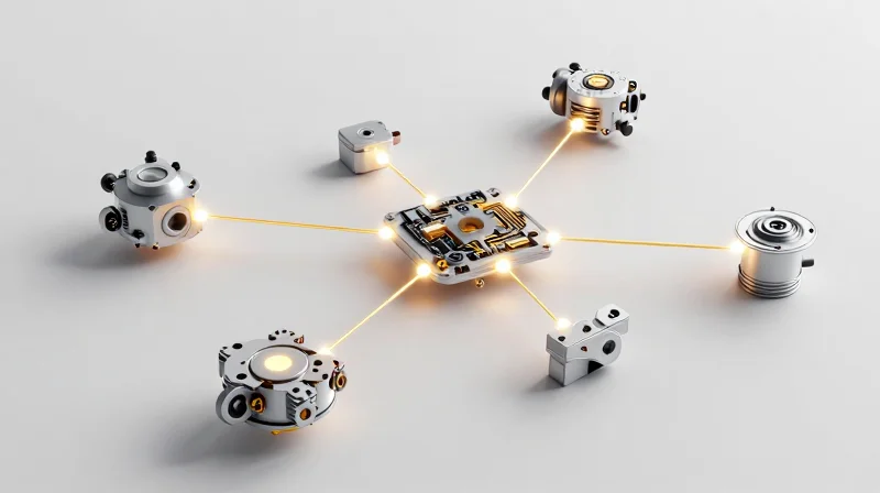
The Strategic Importance of Early-Stage DFM
In the highly regulated landscape of medical device manufacturing, the cost of change increases exponentially as a project moves from design to production. By implementing DFM principles during the initial architectural phase, engineering teams can proactively identify potential assembly bottlenecks, material constraints, and tolerance stacking issues before they manifest as costly manufacturing non-conformances.
Mitigating Risks and Reducing Cycle Times
Early-stage DFM shifts the focus from 'designing for function' to 'designing for reproducible performance.' When technical teams collaborate with manufacturing partners at the outset, they ensure that the box build architecture—including cable routing, board-to-chassis mounting, and enclosure assembly—is optimized for automated processes rather than manual interventions.
| Feature | Reactive Design Approach | Proactive DFM Approach |
|---|---|---|
| Cost of Engineering Changes | High (Production Stage) | Low (Design Stage) |
| Assembly Throughput | Limited by Manual Tweaks | Optimized for Scalability |
| Supply Chain Resilience | Rigid/Proprietary Parts | Standardized/Available Parts |
- How does early DFM impact regulatory validation?
By standardizing assembly processes early, teams produce more consistent, repeatable outputs, which simplifies the verification and validation (V&V) process required for FDA and ISO compliance. - What is the biggest hidden cost in box builds?
The hidden cost lies in 'touch labor'—manual rework, complex cabling configurations, or difficult fastener access points that significantly inflate the final assembly time per unit.
Ultimately, the strategic application of DFM minimizes reliance on tribal knowledge and promotes standardized work instructions. This transformation not only stabilizes production output but also provides the manufacturing agility needed to scale medical device output in response to fluctuating market demands.
Precision Component Integration and Tolerancing
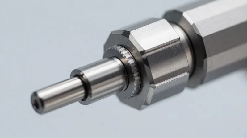
The Role of GD&T in Medical Device Assembly
Geometric Dimensioning and Tolerancing (GD&T) provides a robust mathematical language for engineering, ensuring that critical medical components maintain their intended spatial relationships. Unlike traditional coordinate dimensioning, GD&T accounts for the functional interaction between parts, such as the mounting of high-sensitivity PCB arrays onto chassis standoffs. By defining precise datums and tolerance zones, engineers can eliminate assembly bottlenecks caused by stacking tolerances, which is vital for maintaining signal integrity and device reliability.
Optimizing Fitment Through Tolerance Stack-Up Analysis
Tolerance stack-up analysis is the cornerstone of DFM for medical box builds. As components become increasingly miniaturized, the cumulative effect of individual part variances can lead to board warping, housing interference, or connector misalignment. Employing Worst-Case or Statistical (RSS) analysis allows design teams to predict the likelihood of assembly failure before a single part is machined or molded.
| Tolerance Method | Primary Application | Risk Assessment |
|---|---|---|
| Worst-Case | Mission-Critical Interfaces | High reliability; assumes all parts at extreme limits. |
| Statistical (RSS) | Volume Production | Optimized cost; assumes random distribution of variations. |
Best Practices for Seamless Integration
- How do we minimize connector stress during assembly?
Utilize floating hardware or compliant mounts to absorb minor positional deviations, ensuring that delicate headers and cables are not subjected to mechanical strain. - Why should datums match the final assembly function?
Designing datums based on how the part rests in the final assembly rather than its manufacturing orientation reduces the potential for assembly-level fitment errors. - What is the impact of surface finish on integration?
Surface finish tolerances can significantly affect part fitment; verify that plating or coating thicknesses are accounted for in the overall tolerance loop.
Optimizing Cable Harness Routing for Assembly Speed
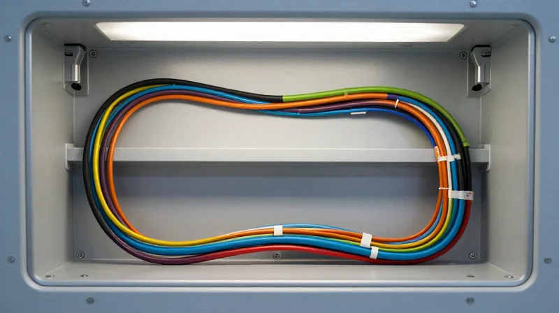
Minimizing Assembly Variance Through Strategic Routing
In high-stakes medical environments, cable harness routing must be deterministic rather than ad-hoc. By designing standardized routing paths that leverage dedicated cable clips, standoffs, or integrated channels, manufacturers can eliminate the 'operator interpretation' factor. This minimizes the risk of pinched wires during chassis closure and prevents cable migration, which could interfere with sensitive optical or electrical components.
Routing Strategy Comparison
| Routing Method | Assembly Efficiency | Serviceability | Cost Impact |
|---|---|---|---|
| Loose Wiring | Low | Difficult | Low |
| Cable Channels | High | Excellent | Medium |
| Custom Brackets | Medium | Good | High |
Improving Field Serviceability
Field serviceability is directly tied to cable accessibility. Engineers should prioritize 'modular harness design,' where sections of the harness can be replaced without stripping the entire unit. Using color-coded connectors and clear, permanent labeling at both ends of each harness segment significantly reduces the Mean Time to Repair (MTTR) and prevents catastrophic reconnection errors.
- How can I prevent cable interference?
Implement physical separation between low-voltage signal lines and high-current power lines using dedicated routing channels and shielded conduit paths. - What is the best way to handle slack?
Design harness lengths with precise tolerances and include specific 'service loops' in predictable, non-obstructive locations to facilitate easier component removal. - How does DFM affect cable strain?
Integrate strain relief features directly into the chassis housing, ensuring that cables are secured at the point of entry to protect sensitive connector pins from physical stress.
Advanced EMI Shielding Techniques

As medical devices become increasingly compact and dense, managing Electromagnetic Interference (EMI) within the enclosure is a critical DFM challenge. Advanced shielding is no longer just about adding bulk metal; it is about precision-engineered containment that integrates seamlessly into the mechanical design, ensuring that sensitive diagnostic signals remain clear of high-frequency noise generated by internal power supplies or processors.
Material Selection for Shielding Effectiveness
| Shielding Material | Key Advantage | Best Application |
|---|---|---|
| Conductive Elastomers | Superior environmental seal | High-humidity enclosures |
| Form-in-Place Gaskets | Automated dispensing | High-volume small-form factors |
| Metalized Fabrics | Lightweight and flexible | Complex, tight-radius routing |
DFM Strategies for Integration
To prevent assembly bottlenecks, EMI solutions must be considered during the initial enclosure design phase. Designers should prioritize 'Board-Level Shielding' (BLS) to capture interference at the source, reducing the dependence on secondary chassis-level shielding which complicates assembly time and mechanical fitment.
Frequently Asked Questions
- How does board-level shielding impact repairability?
Modern modular BLS designs utilize snap-fit or removable covers, allowing technicians to inspect and repair components without the need for thermal desoldering. - Can shielding act as a heat sink?
Yes, many modern conductive gaskets and thermal interface materials (TIMs) provide a dual-purpose path, shunting both heat and electrical noise to the chassis simultaneously. - Why avoid manual shielding tapes in high-volume builds?
Manual application is prone to human error, including uneven surface contact and fatigue, which leads to inconsistent grounding and failures in post-assembly signal integrity testing.
Thermal Management within Sealed Enclosures

Engineering Thermal Paths in Hermetically Sealed Units
When medical enclosures are sealed to meet IP65/IP67 ingress standards, the elimination of airflow necessitates a design shift toward conductive heat transfer. Engineers must leverage the mechanical housing itself as a heat sink, ensuring that heat-generating components are coupled directly to the enclosure frame through high-thermal-conductivity interfaces.
Thermal Interface Material (TIM) Selection
| Material Type | Thermal Conductivity | Best Use Case |
|---|---|---|
| Thermal Pads | Moderate | Filling gaps between PCB and chassis |
| Phase Change Materials | High | High-heat CPUs and power transistors |
| Thermally Conductive Epoxies | Very High | Permanent bonding of small sensors |
Best Practices for Sealed Thermal DFM
Design for Manufacturing in sealed units focuses on assembly precision. Improper application of TIMs—such as trapped air pockets or inconsistent thickness—can create hot spots that degrade electronic components prematurely. Manufacturers should implement automated dispensing of thermal compounds to ensure uniform coverage and optimal contact pressure across the entire thermal stack.
Frequently Asked Questions on Sealed Thermal Management
- How do I calculate the heat dissipation limit for a sealed box?
Use a thermal simulation software to calculate the total power dissipation vs. the thermal resistance of the enclosure material; generally, passive cooling in sealed plastic units is limited to under 10W without dedicated heat pipes. - Can I use internal heat sinks in a sealed design?
Yes, but they are only effective if linked to the external chassis via thermal bridges or if the internal volume is large enough to allow for internal convective loops. - Does EMI shielding negatively impact thermal performance?
Yes, standard metal shielding cans can trap heat; DFM best practice involves using thermally conductive EMI gaskets or integrating the shield directly into the main thermal path.
Ensuring Regulatory Compliance via Design Consistency
Standardized DFM as a Regulatory Foundation
In the highly regulated medical device market, compliance is not an add-on but a fundamental output of the design process. By embedding regulatory requirements directly into DFM checklists, engineering teams minimize variability—a critical factor in successful FDA submissions and ISO 13485 audits. Consistent design practices ensure that every enclosure, cable route, and PCB assembly meets pre-validated safety and performance standards from the prototype stage through full-scale production.
Compliance Benefits of DFM Consistency
| Requirement Area | DFM Standardization Approach | Impact on Regulatory Audits |
|---|---|---|
| Material Traceability | Uniform BOM structures and standardized part numbering | Simplifies supply chain audits and recall management |
| Process Validation | Consistent assembly tolerances and torque specifications | Reduces OQ/PQ variation, speeding up validation cycles |
| Document Control | Automated DFM rule checks and standardized drawing formats | Ensures all design changes are captured in the DHF/DMR |
Facilitating Faster FDA and ISO Approval Cycles
When DFM practices are harmonized, the 'Design History File' (DHF) becomes a natural extension of the engineering workflow rather than a retrospective administrative burden. Auditors assess the robustness of the manufacturing process; standardized DFM allows manufacturers to prove that the 'Design for Manufacture' is inherently tied to the 'Design for Safety.' This transparency significantly reduces requests for additional information (RAIs) during submission.
- How does DFM minimize audit risks?
By enforcing standardized build processes, DFM ensures that manufacturing outputs strictly adhere to the validated design specifications, leaving no room for unauthorized, undocumented deviations. - Why is material selection critical in DFM?
For medical devices, material compliance (biocompatibility, flame retardancy) is non-negotiable. Standardized DFM libraries ensure that only pre-vetted, compliant materials are selected during the design phase. - Can DFM consistency prevent production delays?
Yes. Consistent assembly methods prevent rework and quality escapes, ensuring that the production line remains in a state of 'validated control,' which is a requirement for ISO 13485 certification.
The Role of Automation in Medical Box Builds

Automation within medical box builds is no longer merely a means to increase speed; it is a critical strategy for ensuring process repeatability and minimizing human variability in sensitive assembly environments. By deploying targeted automation, manufacturers can reduce the risks of physical contamination, torque inaccuracies, and repetitive strain, all while maintaining the stringent quality standards required for ISO 13485 compliance.
Determining the Automation Threshold
Not every task in a medical box build warrants automation. The decision must be predicated on a cost-benefit analysis involving batch size, the complexity of tactile feedback required, and the criticality of the specific component. High-volume, repeatable tasks like screw driving, label application, and optical inspection are primary candidates for automation, while intricate cable routing or delicate sensor placement often benefit from the human hand's intuitive dexterity.
| Process Task | Best Approach | Reasoning |
|---|---|---|
| Precision Fastening | Automated | Ensures consistent torque and data logging. |
| Wire Management | Manual | Requires spatial awareness and sensitivity to strain. |
| Functional Testing | Automated | Eliminates operator bias in pass/fail validation. |
| Cosmetic Inspection | Hybrid | Automated for surface defects, manual for aesthetic nuance. |
FAQs on Implementing Automated Assembly
- How does automation impact regulatory audit trails?
Automated systems inherently provide digital logs of critical parameters, such as torque values and test results, which significantly simplify documentation for FDA and ISO 13485 audits. - Is automation appropriate for high-mix, low-volume (HMLV) medical devices?
While traditional rigid automation is cost-prohibitive for HMLV, flexible systems like collaborative robots (cobots) can be reprogrammed easily, making them increasingly viable for varied production runs. - What is the biggest risk of introducing automation into medical box builds?
The primary risk is over-engineering. Automating a process without sufficient volume or without accounting for component tolerance variations can introduce more downtime and maintenance complexity than manual assembly.
Continuous Improvement through Post-Build Data Analysis
Continuous Improvement through Post-Build Data Analysis
The assembly of medical box builds should not be viewed as a static event but as a dynamic process that evolves with real-world performance feedback. By integrating post-build yield metrics, failure analysis, and field-performance data back into the DFM (Design for Manufacturing) loop, manufacturers can identify latent structural risks and optimize assembly sequences to mitigate quality drift.
Data-Driven Process Optimization
| Data Source | Key Indicator | Assembly Optimization Goal |
|---|---|---|
| In-Circuit Test (ICT) | Component failure rates | Adjusting board mounting torque tolerances |
| Visual Inspection | Solder joint irregularities | Fine-tuning robotic dispensing profiles |
| Field Returns | Seal integrity breaches | Modifying gasket compression protocols |
Establishing a Closed-Loop Feedback Cycle
To achieve seamless assembly optimization, establish a formal feedback mechanism where production anomalies are categorized and mapped against the original DFM intent. This ensures that every deviation is analyzed not just for rework, but for potential design adjustments that simplify assembly while maintaining compliance standards.
- How does failure analysis impact DFM?
Root cause analysis reveals whether a failure stems from part variability or process limitations, allowing engineers to update DFM guides to favor more robust components or jigs. - Why is long-term yield data critical for medical builds?
Medical devices demand ultra-high reliability. Longitudinal yield data identifies slow-onset trends, such as thermal fatigue, before they trigger critical field failures. - How can I integrate post-build data into regulatory workflows?
Documenting yield-based process improvements provides objective evidence of 'Quality by Design' compliance, which is highly valued during ISO 13485 and FDA audits.
Optimizing your DFM strategy is a critical investment in your medical device’s success, ensuring that high-performance designs translate into reliable, mass-produced instruments. By focusing on component integration, signal integrity, and assembly efficiency, you can significantly enhance your product’s yield and longevity. Contact our engineering team today to audit your design for manufacturing readiness and accelerate your time-to-market.
