
In today’s competitive electronics market, the intersection of miniaturization and reliability is where your product either succeeds or fails. Traditional rigid board assemblies with complex cabling often lead to high failure rates and ballooning production costs. By adopting TWS high-precision rigid-flex PCB solutions, engineers can consolidate components, simplify supply chains, and unlock superior structural integrity for mission-critical applications.
Understanding the True Cost of Traditional PCB Interconnects

The Hidden Burden of Traditional Interconnects
In many contemporary electronic systems, the reliance on mechanical connectors, bulky ribbon cables, and intricate wire harnesses acts as a major bottleneck for both production efficiency and field reliability. While these components are often viewed as simple, modular solutions, they introduce mechanical vulnerabilities and supply chain complexities that disproportionately inflate the Total Cost of Ownership (TCO). By utilizing TWS High-Precision Rigid-Flex PCB solutions, designers can eliminate these transitional points, directly addressing the primary failure modes associated with physical contact degradation.
Comparative Analysis: Traditional vs. Rigid-Flex Integration
| Attribute | Traditional Interconnects | TWS Rigid-Flex Integration |
|---|---|---|
| Assembly Labor | High (Manual Insertion) | Low (Automated SMT) |
| Failure Points | Multiple (Crimp/Solder Joints) | Minimal (Integrated Circuitry) |
| Vibration Resilience | Poor (Connectors Loosen) | Excellent (Monolithic Structure) |
| Signal Integrity | Variable (Contact Resistance) | High (Consistent Impedance) |
Addressing Common Interconnect Challenges
- Why do mechanical connectors frequently fail in the field?
Mechanical connectors are highly susceptible to fretting corrosion, oxidation, and mechanical loosening due to thermal cycling and vibration. Every connector interface represents a distinct point of contact resistance that inevitably degrades over time. - How do wire harnesses affect assembly overhead?
Wire harnesses require significant manual routing, cable management, and individual connection steps, which increase touch time and the risk of human error during assembly. These processes are inherently labor-intensive and difficult to scale. - Can Rigid-Flex solutions actually reduce overall production costs?
Yes. While the unit cost of a Rigid-Flex board is higher, the ROI is maximized through the elimination of separate connectors, reduced assembly time, lower inventory management costs, and significantly lower warranty claim rates due to increased reliability.
The Anatomy of High-Precision Rigid-Flex Technology
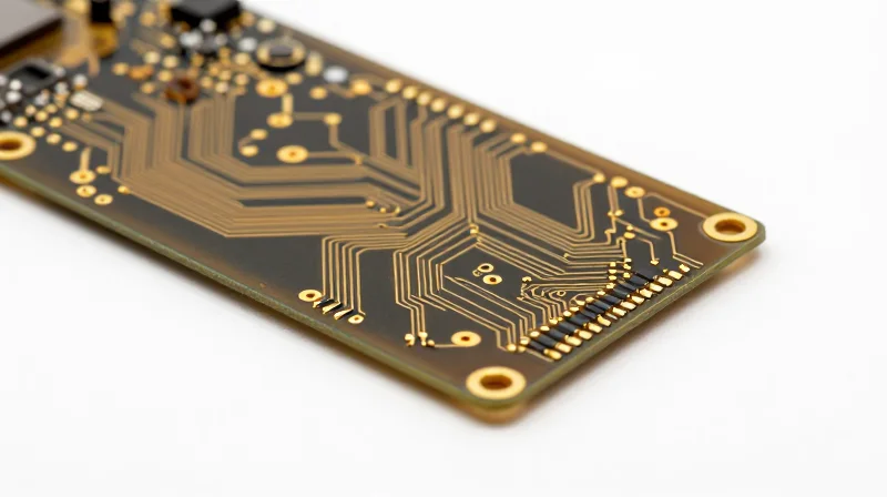
The Engineering Foundation of TWS Rigid-Flex
Unlike standard rigid-flex assemblies that rely on generic adhesives and inconsistent lamination cycles, TWS high-precision circuits are built on a foundation of proprietary materials science. By utilizing modified polyimide (PI) substrates and precision-controlled coverlay lamination, we eliminate the CTE (Coefficient of Thermal Expansion) mismatch that typically causes micro-cracking and delamination during high-stress thermal cycling.
Material Performance Comparison
| Feature | Standard Flex | TWS High-Precision |
|---|---|---|
| Adhesive System | Acrylic/Epoxy | Adhesiveless Bondply |
| Thermal Stability | Moderate | Superior (High Tg) |
| Dimensional Stability | Variable | Precision Controlled |
| Interconnect Reliability | Connector Dependent | Integrated Solderless |
Optimizing Signal Integrity and Physical Robustness
TWS technology utilizes advanced laser-direct imaging (LDI) and selective plating processes that ensure uniform copper cross-sections across the flexible transition zones. This precision prevents 'necking'—a common failure mode in traditional circuits where copper thins out under bend radii—thereby extending the operational life of the assembly under constant mechanical strain.
- How does TWS reduce assembly labor?
By integrating the interconnect structure directly into the PCB substrate, TWS removes the need for manual cable routing, connector soldering, and bulky harness housing, reducing assembly time by up to 40%. - Why do TWS circuits exhibit lower failure rates?
Our high-precision manufacturing eliminates intermittent mechanical contacts, which are the primary source of 'no-fault-found' (NFF) errors in high-vibration applications. - Is the TWS process compatible with high-speed signals?
Yes, our precise dielectric thickness control ensures matched impedance performance throughout the transition from rigid to flex zones, maintaining signal integrity far better than wire-based alternatives.
Slash Assembly Labor through Design Consolidation
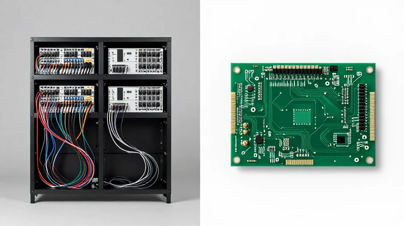
The Hidden Costs of Multi-Board Architectures
Traditional electronic designs often rely on a modular approach using multiple rigid PCBs connected by bulky wire harnesses, ribbon cables, or board-to-board connectors. While modularity offers a perceived benefit for prototyping, it introduces significant hidden labor costs during production. Every connector represents a potential failure point that requires manual labor for assembly, inspection, and testing. TWS High-Precision Rigid-Flex technology solves this by integrating these interconnects directly into the substrate, allowing for a monolithic design that replaces dozens of discrete parts with a single, seamless circuit.
Comparative Efficiency: Multi-Board vs. Rigid-Flex
| Assembly Metric | Traditional Multi-Board | TWS Rigid-Flex Solution |
|---|---|---|
| Manual Soldering Steps | High (Many Connectors) | Minimal (Integrated) |
| Mechanical Interconnects | Required (Ribbons/Cables) | Eliminated |
| Human Error Risk | Significant | Negligible |
| Total Assembly Time | Extended | Reduced by up to 60% |
Strategic Advantages of Design Consolidation
Beyond the immediate reduction in labor hours, design consolidation facilitates a more streamlined supply chain and simplified final assembly. By reducing the bill of materials (BOM), you diminish the logistical complexity of sourcing connectors and cable assemblies. Furthermore, the inherent precision of TWS rigid-flex circuits ensures that electrical pathways are consistent, removing the variability introduced by manual wiring during high-volume production.
- How does rigid-flex reduce touch labor?
It eliminates the need for manual connection of ribbon cables, wire harnesses, and board-to-board connectors, which are the most time-consuming aspects of assembly. - Does consolidation impact inspection time?
Yes, it significantly reduces the time required for Quality Assurance, as there are fewer solder joints and mechanical interfaces to inspect for potential defects. - Is the design process more complex?
While it requires upfront precision engineering, the long-term ROI is realized through a drastic reduction in manufacturing cycle times and field failure rates.
Eliminating Points of Failure: Improving Long-Term Reliability
Removing Mechanical Vulnerabilities
The integration of rigid-flex technology inherently removes the most common failure points in complex electronic assemblies: mechanical connectors and solder joints. Traditional interconnects are susceptible to vibration, thermal cycling, and physical shock, which lead to intermittent contact, fretting, and eventual signal loss. TWS high-precision rigid-flex designs utilize a monolithic structure, effectively turning vulnerable wiring pathways into a singular, durable circuit that resists mechanical fatigue.
Comparison of Interconnect Failure Risks
| Failure Factor | Discrete Connectors/Wiring | TWS Rigid-Flex Integration |
|---|---|---|
| Mechanical Fatigue | High risk at stress points | Negligible (solid-state path) |
| Oxidation/Corrosion | High (exposed mating surfaces) | Low (sealed conductive layers) |
| Contact Resistance | Variable/Increases over time | Stable (metallurgically bonded) |
| Vibration Impact | Prone to fretting corrosion | Immune due to structural unity |
Ensuring Long-Term Signal Integrity
Beyond physical robustness, rigid-flex circuits offer superior electrical stability. Standard connectors accumulate microscopic debris and oxide layers that increase contact resistance, causing signal degradation. TWS engineered rigid-flex boards eliminate these interfaces entirely. By replacing multiple wire-to-board connections with a continuous copper trace path, we provide a reliable, low-impedance electrical environment that maintains signal integrity throughout the entire life of the device.
Frequently Asked Questions
- How does eliminating connectors improve long-term ROI?
Reduced connector counts lower the risk of warranty claims and field failures, which directly offsets the cost of the rigid-flex board compared to traditional assembly components. - Can rigid-flex withstand high-vibration environments?
Yes, because the assembly is a unified structure, it lacks the discrete mating parts that typically loosen or fail under constant vibration or shock. - Does the elimination of manual wiring improve manufacturing throughput?
Absolutely; moving from multi-component wiring to a single rigid-flex circuit reduces assembly time, decreases human error during inspection, and simplifies the supply chain.
Miniaturization and Space Optimization Strategies

Advanced Miniaturization Through 3D Integration
Miniaturization is no longer just about shrinking components; it is about reclaiming wasted volume through 3D architectural design. By transitioning from flat, multi-board configurations to integrated rigid-flex structures, engineers can fold circuitry within the physical constraints of an enclosure. This approach eliminates the necessity for bulky, space-consuming connectors and cabling, effectively increasing board density without violating thermal management requirements.
Performance Metrics: Rigid-Flex vs. Traditional Interconnects
| Parameter | Traditional Multi-Board | TWS Rigid-Flex Solution |
|---|---|---|
| Z-Axis Profile | High (Connector dependent) | Low (Low-profile folding) |
| Mechanical Volume | Increased by connectors | Optimized by form-fitting |
| Signal Loss | High (Connector interface) | Minimal (Integrated traces) |
| Assembly Footprint | Large | Compact/3D stacked |
Strategic Optimization for Thermal and Signal Integrity
Space optimization strategies must account for heat dissipation and high-speed signal integrity. TWS high-precision manufacturing allows for localized copper thinning or thermal vias positioned specifically at high-heat zones. By removing intermediate connection points, we drastically reduce insertion loss and cross-talk, ensuring that smaller footprints do not translate to degraded electrical performance.
Frequently Asked Questions
- Does folding rigid-flex boards increase thermal failure risks?
No, if designed correctly. TWS utilizes precision material selection to ensure that thermal path conductivity is maintained through the flex sections, often improving heat dissipation compared to separate boards connected by cables. - How does rigid-flex design help in reducing assembly footprints?
By replacing heavy mechanical connectors with integrated flexible transition zones, the board footprint is reduced by eliminating keep-out areas required for connector mating and cable routing. - Is signal integrity compromised in high-density flex zones?
Quite the opposite. Eliminating connector interfaces removes common sources of impedance discontinuity, which actually enhances signal integrity for high-speed data transmissions.
Supply Chain Efficiency and Part Reduction
Streamlining the Bill of Materials (BOM) Through Integration
A primary driver of hidden manufacturing costs is the proliferation of discrete components and bulky interconnects. TWS rigid-flex circuits replace multiple rigid boards, ribbon cables, and mechanical connectors with a monolithic architecture. By eliminating these secondary parts, manufacturers can achieve a significant reduction in the BOM, which directly translates to lower procurement costs, fewer line items to track, and reduced overhead for quality control.
| Component Category | Traditional Assembly | TWS Rigid-Flex Solution |
|---|---|---|
| Connectors | Multiple per unit | Zero (direct integration) |
| Cabling/Ribbons | High manual routing | None (embedded routing) |
| Soldering Points | High risk of defects | Minimal, automated |
| Total Part Count | High | Low |
Impact on Inventory and Time-to-Market
Reducing the number of parts is not just an exercise in cost-cutting; it is a strategic approach to operational efficiency. Fewer SKUs mean simplified logistics and a leaner supply chain, which is critical in an era of global material shortages. By integrating functionality into the PCB design early in the development cycle, TWS solutions enable faster assembly times and more reliable product testing, ensuring that innovative products reach the market faster with a reduced risk of supply chain disruptions.
Frequently Asked Questions
- How does part reduction impact assembly labor costs?
By removing mechanical connectors and manual cabling, assembly labor is reduced by eliminating repetitive manual insertion steps, lowering the total man-hours required per unit. - Can rigid-flex PCBs actually replace complex cable harnesses?
Yes. Integrated copper traces within the flexible layer serve as a high-density, reliable replacement for traditional wire harnesses, improving signal integrity while saving space. - Does a smaller BOM increase long-term reliability?
Absolutely. Every connection point is a potential point of failure. Reducing the number of connectors significantly lowers risks associated with oxidation, mechanical stress, and intermittent contact issues.
Quality Assurance and Testing Protocols for Complex Boards

Multi-Layered Testing Framework
To achieve zero-defect assembly cycles, TWS utilizes an integrated testing methodology that transitions from raw material verification to final functional validation. By detecting anomalies during the fabrication process—rather than at the final assembly stage—manufacturers significantly reduce costly scrap rates and rework cycles.
| Testing Protocol | Purpose | Failure Mitigation Target |
|---|---|---|
| AOI (Automated Optical Inspection) | Surface mount and solder joint verification | Short circuits and misalignment |
| Flying Probe Testing | Net connectivity validation | Open circuits and latent defects |
| Thermal Shock/Cycle Testing | Simulating environmental stress | Via barrel cracking and delamination |
| TDR (Time Domain Reflectometry) | Impedance consistency checking | High-speed signal degradation |
Quality Assurance FAQs
- How does early-stage testing impact ROI?
Identifying structural defects at the bare-board level prevents the costly integration of faulty circuits into expensive final assemblies, ensuring that ROI is maximized through yield optimization. - Why is stress testing critical for rigid-flex boards?
Rigid-flex assemblies often endure dynamic mechanical stress; periodic thermal cycling ensures that the interface between rigid and flexible layers remains robust throughout the product lifecycle. - Can TWS customization include specific industry protocols?
Yes, our testing protocols are adaptable to meet rigorous IPC Class 3 standards, military-grade requirements, or bespoke automotive qualification parameters to suit your specific application.
Ultimately, the precision of testing protocols serves as the final safeguard for high-density, complex boards. By aligning manufacturing tolerances with advanced diagnostic feedback, TWS guarantees that rigid-flex solutions perform reliably in the most demanding operational environments.
Calculating the ROI: Long-Term Financial Advantages
Beyond Unit Cost: The Total Cost of Ownership Framework
The true financial value of TWS high-precision rigid-flex PCBs is realized by evaluating the Total Cost of Ownership (TCO). While the raw substrate cost may be higher than traditional rigid alternatives, the consolidated design significantly lowers procurement, assembly, and field failure expenses. By integrating multiple rigid sections with flexible interconnects, engineers eliminate the need for costly connectors, cabling harnesses, and labor-intensive assembly processes, resulting in a leaner BOM and higher production throughput.
| Metric | Traditional Rigid Assembly | TWS Rigid-Flex Solution |
|---|---|---|
| Connector Count | High | Minimal |
| Assembly Labor | Intensive | Automated |
| Failure Point Risk | High (Solder/Cables) | Low (Integrated) |
| Maintenance Needs | Frequent | Minimal |
Quantifying Long-Term Financial Gains
To calculate the projected return on investment, organizations should analyze three primary financial drivers: reduced assembly cycle times, lower field return rates, and the elimination of logistics overhead. Precision engineering minimizes scrap rates during surface mount technology (SMT) processes, while the increased reliability extends the product lifecycle, thereby reducing warranty reserves. The following formula represents the net advantage: *Net ROI = (Saved Assembly Costs + Reduced Failure Costs + Logistics Savings) - (Premium PCB Investment)*.
- How does rigid-flex reduce warranty expenses?
By replacing mechanical connectors and fragile wire harnesses with a singular, robust circuit, the likelihood of intermittent contact failure or vibration-induced breakage is nearly eliminated, leading to significant long-term warranty savings. - What is the impact on inventory management?
Consolidating multiple components into one integrated rigid-flex board simplifies procurement and inventory logistics, reducing the administrative burden and costs associated with tracking multiple part numbers. - Can TWS solutions accelerate ROI through speed-to-market?
Yes, by streamlining the physical architecture, design cycles are simplified and production integration is accelerated, allowing for faster market entry and a more rapid realization of product revenue.
Transitioning to rigid-flex technology is more than an engineering upgrade; it is a strategic business decision that optimizes both performance and profitability. By reducing assembly complexity and inherent failure points, you protect your bottom line while delivering a superior product to your customers. Ready to optimize your manufacturing? Contact our TWS engineering team today to discuss your next project.
