
In the race to build smaller, faster, and more reliable electronics, rigid-flex PCBs have become the backbone of modern innovation. However, moving from prototype to production requires more than just a schematic—it requires a manufacturing partner capable of executing complex multi-layer interconnects with extreme precision. In this guide, we break down how to evaluate vendors to ensure your design transitions seamlessly from the lab to the field.
Evaluating Material Reliability and Standards
The Primacy of IPC-6013 Compliance
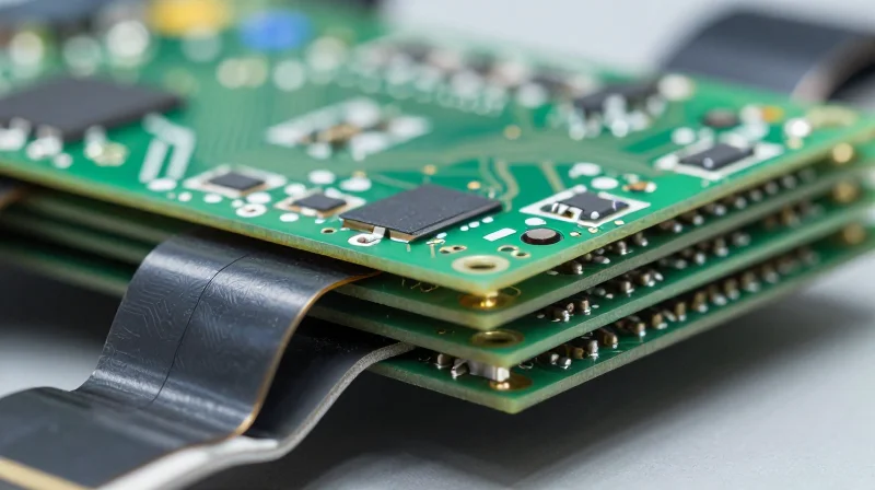
For rigid-flex designs, IPC-6013 is the industry benchmark that defines the qualification and performance requirements for flexible printed boards. Manufacturers must demonstrate mastery of this standard, specifically regarding the classification of board types—from simple flexible circuits to complex multilayer rigid-flex assemblies. When selecting a partner, demand proof of certification or documented compliance reports to ensure the facility maintains consistent manufacturing processes that account for the unique mechanical stresses inherent in your compact design.
Verifying Material Compatibility for Dynamic Bending
Dynamic bending applications require materials that can withstand millions of cycles without material degradation or fatigue-induced fracturing. Selecting the right substrate involves evaluating the Coefficient of Thermal Expansion (CTE), moisture absorption rates, and peel strength. Engineers must collaborate with manufacturers to ensure that polyimide adhesives, coverlays, and stiffeners are chemically and mechanically compatible with the copper foil types used.
| Material Property | Importance for Dynamic Bending | Key Metric for Evaluation |
|---|---|---|
| Copper Foil Type | Determines fatigue life under repeated movement. | Rolled-Annealed (RA) vs. Electro-Deposited |
| Dielectric Thickness | Controls bending radius and mechanical stress. | Measured in mils (e.g., 0.5 to 2.0 mil polyimide) |
| Adhesive System | Prevents delamination during thermal cycling. | Glass Transition Temperature (Tg) |
Frequently Asked Questions
- Why is IPC-6013 critical for rigid-flex designs?
It sets the standard for structural integrity, ensuring that the transition areas between rigid and flex regions are correctly fabricated to prevent common failure points like trace cracking or interlayer delamination. - How can I assess a manufacturer’s reliability during the selection phase?
Request a 'Design for Manufacturing' (DFM) audit report from previous projects, examine their material supply chain certifications (UL, ISO), and inquire about their internal testing protocols for bend-cycle life. - What is the primary difference between static and dynamic bending materials?
Static applications utilize materials designed for infrequent flexing during installation, whereas dynamic applications require specialized polyimides and RA copper foils engineered to endure high-frequency repetitive movement over the product life cycle.
The Critical Role of Trace Impedance Control

The Challenge of Impedance Consistency in Rigid-Flex Transitions
Maintaining uniform characteristic impedance in a rigid-flex design is inherently difficult due to the disparity in dielectric constants and layer stack-up configurations between rigid FR-4 and flexible polyimide substrates. As signals travel from a rigid area through the bend radius of the flex section, any discontinuity in trace width, copper thickness, or material dielectric property triggers signal reflections, crosstalk, and increased insertion loss.
Key Factors Influencing Impedance Stability
| Parameter | Impact on Impedance | Mitigation Strategy |
|---|---|---|
| Dielectric Constant (Dk) | High variance causes signal speed fluctuation | Match Dk values across rigid/flex materials |
| Trace Geometry | Width variation shifts impedance targets | Apply laser-direct imaging (LDI) for precision |
| Coverlay Adhesive | Adhesive flow alters capacitance | Use low-flow or no-flow adhesive systems |
Ensuring Manufacturing Precision
To achieve high-precision control, the manufacturer must possess advanced etching capabilities that account for the 'etch factor' specific to flexible laminates. Because flexible circuits often require thinner copper to maintain pliability, the etching process becomes more sensitive to chemical over-etching, which can shrink trace widths beyond acceptable tolerances. Selecting a manufacturer with automated optical inspection (AOI) integrated into the lamination cycle is essential for validating these narrow tolerances before final bonding.
- How does the coverlay impact impedance?
The coverlay and the adhesive required to bond it to the circuit add dielectric material that significantly alters the local impedance environment, requiring the manufacturer to adjust trace geometry in the CAD model specifically for the flex regions. - Why is layer registration critical for impedance?
In high-speed differential pairs, misalignment between signal layers and reference planes changes the coupling, which directly causes impedance spikes that degrade signal eye diagrams. - Should I require impedance coupon testing?
Yes, demanding TDR (Time Domain Reflectometry) testing on dedicated coupons located on the manufacturing panel is the only objective way to verify that the target impedance was met across the transition zones.
Complexity Management: Navigating Layer Counts

Complexity Management: Navigating Layer Counts
Managing layer counts in ultra-compact rigid-flex designs requires a precise balance between signal density, thermal management, and mechanical longevity. As the number of flex layers increases, the assembly becomes significantly more prone to fatigue failure at the transition zones if the stack-up geometry is not carefully engineered.
Trade-offs in High-Density Interconnects
| Layer Count | Complexity Level | Mechanical Constraint | Recommended Application |
|---|---|---|---|
| 1-2 Layers | Low/Moderate | Highly Flexible | Simple sensors, small interconnects |
| 3-6 Layers | High | Moderate Flexibility | Advanced wearables, handheld devices |
| 8+ Layers | Ultra-High | Limited/Static Flex | Medical implants, military/aerospace |
To maintain structural integrity as layer counts rise, engineers must prioritize 'bookbinder' construction or neutral-axis stack-up design. These techniques ensure that the innermost flex layers are not subject to excessive stress during bending cycles. A manufacturer’s ability to execute these complex stack-ups is a key indicator of their technical maturity.
FAQ: Strategic Considerations for High-Layer Rigid-Flex
- How does layer count impact bend radius?
As layer count increases, the thickness of the flexible circuit increases proportionally, which significantly expands the minimum required bend radius. You must balance signal routing needs with the physical space constraints of your enclosure. - When is it necessary to use staggered vias in the flex area?
Staggered vias are essential in high-layer count designs to prevent stress concentrations. Aligning vias vertically creates a 'perforation' effect that significantly weakens the flex material, leading to premature copper cracking. - What role does adhesive play in high-density stack-ups?
Adhesive-less materials are mandatory for high-precision, high-layer count designs. Adhesives increase the total thickness and decrease the modulus of the material, making it harder to control impedance and reducing the overall mechanical reliability of the flex section.
Assessing Manufacturer Technical Certifications
For ultra-compact designs in high-stakes sectors like aerospace, medical, and defense, standard manufacturing qualifications are insufficient. You must verify that your partner holds certifications that validate their internal quality management systems (QMS), risk management protocols, and chain-of-custody security. These credentials provide objective proof that a manufacturer can deliver the consistency required for life-critical or mission-critical hardware.
Core Certifications for High-Reliability Sectors
| Certification | Target Industry | Primary Value Proposition |
|---|---|---|
| AS9100 | Aerospace & Defense | Stringent traceability and robust risk mitigation in complex assemblies. |
| ISO 13485 | Medical Devices | Strict documentation for regulatory compliance and patient safety. |
| ITAR | Defense & Military | Data sovereignty and controlled access to sensitive technical designs. |
Evaluating Compliance and Operational Impact
- Why does AS9100 go beyond standard ISO 9001?
AS9100 builds upon the ISO 9001 framework by adding specialized requirements for aerospace, emphasizing rigorous document control, defect prevention, and full-cycle traceability for every component. - Is ITAR compliance necessary for non-military compact electronics?
If your design incorporates technology classified under the US Munitions List (USML), ITAR compliance is mandatory. Even for commercial projects, choosing an ITAR-compliant facility ensures higher levels of data security and intellectual property protection. - How does ISO 13485 influence rigid-flex design?
This standard forces a disciplined approach to process validation. For medical rigid-flex, this means every bending cycle and material choice is documented to meet clinical regulatory standards, reducing the risk of product recalls.
When auditing a potential manufacturer, never rely on a web-badge alone. Request their most recent audit reports and verify the status through the official certifying body's database. Ensure that the scope of their certification covers the specific manufacturing site where your rigid-flex PCBs will be fabricated, as certificates are often location-specific.
Design for Manufacturing (DFM) Support

The Role of Early-Stage DFM Collaboration
For ultra-compact designs, DFM is not merely a checklist; it is a collaborative engineering process. A high-precision manufacturer should engage with your team during the schematic and layout phases to validate trace geometry, via structures, and bend radius requirements. By integrating DFM early, you can avoid common issues like inconsistent copper distribution in the flex regions or improper stack-up designs that jeopardize long-term reliability.
Key DFM Capabilities for Rigid-Flex Success
| Feature | DFM Focus Area | Impact on Reliability |
|---|---|---|
| Transition Zone | Adhesive distribution and stress relief | Prevents layer delamination during bending |
| Via-in-Pad | Plating thickness and aspect ratio | Ensures connectivity in high-density regions |
| Copper Balancing | Symmetric stack-up design | Reduces thermal warping and mechanical stress |
Evaluating Your Partner’s DFM Workflow
- How do they communicate design violations?
A high-quality partner provides specific, actionable feedback rather than generic error codes, often offering redlined design files or suggestions to optimize cost without compromising performance. - What tools facilitate their DFM feedback loop?
Look for manufacturers who utilize automated DFM software integrated with their internal fabrication processes, ensuring that simulated manufacturability matches real-world facility capabilities. - Do they provide board-level reliability modeling?
The best partners offer simulation data regarding mechanical stress and thermal performance for the rigid-to-flex interface, providing peace of mind for mission-critical applications.
Ultimately, selecting a manufacturer with a robust DFM feedback loop minimizes iterations and accelerates your time-to-market. Prioritize partners who view your project as a partnership and demonstrate an willingness to adapt their fabrication tolerances to meet the unique constraints of your compact electronic system.
Scalability: From Prototype to Mass Production
Ensuring Scalability in Rigid-Flex Manufacturing
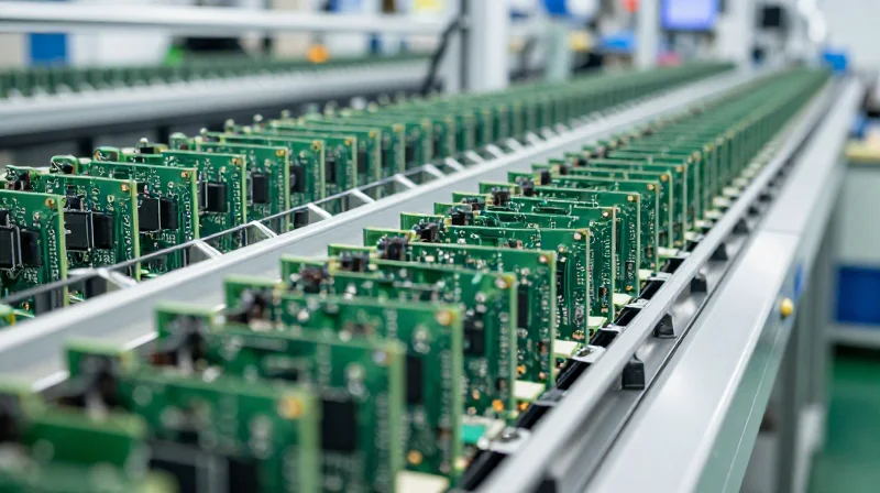
Scalability is not merely about capacity; it is about maintaining exact tolerances and reliability across thousands of units. When scaling rigid-flex designs, the primary risk is process drift, where minor variations in adhesive curing, copper etching, or laser drilling alignment result in cumulative defects. A capable manufacturing partner must demonstrate process stability and automated inspection capabilities that remain consistent regardless of volume.
Scaling Metrics Comparison
| Parameter | Prototype Focus | Production Focus |
|---|---|---|
| Tooling | Soft tooling / Laser cutting | Hard tooling / Progressive stamping |
| Inspection | Manual optical inspection | Automated Optical Inspection (AOI) |
| Process Control | Single-batch validation | Statistical Process Control (SPC) |
| Yield Strategy | High-touch rework capability | Root cause analysis and automation |
Key Considerations for Seamless Scaling
- Does the manufacturer utilize Statistical Process Control (SPC)?
A high-precision partner should employ real-time SPC to monitor critical parameters like impedance variance and registration accuracy throughout the production run, ensuring early detection of process deviations. - How does the facility handle batch-to-batch consistency?
Ensure they utilize standardized material sourcing and maintain a fixed manufacturing process document (MPD) so that mass production runs match the performance characteristics of your golden-sample prototype. - What is the transition process from prototype to NPI?
Ask for their New Product Introduction (NPI) workflow, which should bridge the gap between initial low-volume testing and volume manufacturing, specifically identifying tooling transitions and DFM refinements.
Ultimately, the right partner for your ultra-compact electronic design is one that views volume not as a hurdle, but as a commitment to refined precision. Prioritize manufacturers who can transparently show their scaling trajectory and demonstrate a mature infrastructure for high-volume rigid-flex fabrication.
Supply Chain Resilience and Global Logistics
Assessing Supply Chain Resilience and Transparency
For high-precision rigid-flex designs, the complexity of the bill of materials (BOM) leaves manufacturers vulnerable to component shortages and geopolitical disruptions. A reliable PCB manufacturer must demonstrate proactive supply chain management rather than reactive troubleshooting. This requires transparent access to their procurement strategies, inventory health, and multi-source verification processes to prevent project stalls.
Logistics and Proximity Impact
| Logistics Strategy | Key Advantage | Primary Risk |
|---|---|---|
| Onshoring/Nearshoring | Faster communication and shorter lead times. | Higher initial production costs. |
| Offshoring/Global | Lower unit cost at high volumes. | Long lead times and geopolitical volatility. |
Frequently Asked Questions on Logistics
- How does vendor location affect rigid-flex quality control?
Proximity allows for easier on-site audits and rapid engineering changes. For ultra-compact designs, being able to resolve technical discrepancies in the same time zone can prevent weeks of production delays. - What documentation should I request to verify supply chain transparency?
Ask for their conflict mineral reporting, proof of long-term partnership agreements with base material suppliers (such as polyimide manufacturers), and their contingency plans for hazardous material shortages. - Does the manufacturer maintain safety stock for critical materials?
A high-precision partner should offer a managed inventory program, maintaining a safety stock of proprietary substrates or specialized connectors to insulate your project from sudden supply fluctuations.
Selecting a manufacturing partner for complex rigid-flex designs is a high-stakes decision that dictates the reliability and success of your end product. By prioritizing technical expertise, adherence to rigorous material standards, and scalability, you can effectively de-risk your production pipeline. Ready to elevate your next project? Contact our engineering team today for a comprehensive design-for-manufacturability audit.
