
In the high-stakes world of commercial drone operation, a single electronics failure can lead to catastrophic mission loss. As flight controllers face relentless mechanical stress, thermal fluctuations, and high-frequency vibrations, your choice of PCB substrate and assembly technique is the deciding factor between a reliable workhorse and an airborne liability.
Understanding the Operational Environment
The Mechanics of Operational Stress
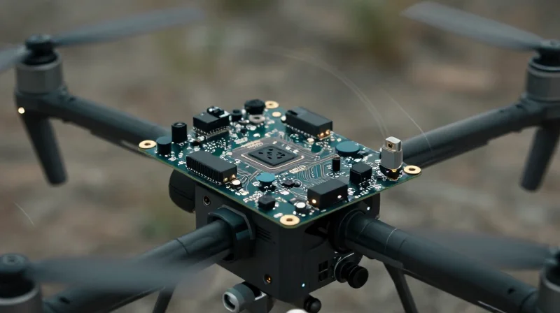
In commercial drone applications, the flight controller acts as the central nervous system. Exposure to sustained high-frequency vibrations from propulsion systems, abrupt G-force shifts during maneuvers, and rapid thermal cycling creates a challenging environment where standard electronic assemblies often fail via solder joint fatigue, micro-cracking, or via-barrel ruptures.
Environmental Stress Factors
| Stress Factor | Primary Failure Mechanism | Mitigation Requirement |
|---|---|---|
| High-Frequency Vibration | Solder joint fatigue | High-Tg substrate materials |
| G-Force Maneuvers | Component delamination | Enhanced mechanical retention |
| Thermal Cycling | CTE mismatch | Balanced copper weighting |
Frequently Asked Questions
- Why is the Glass Transition Temperature (Tg) critical?
A high-Tg material ensures the PCB remains rigid and maintains structural integrity when exposed to the heat generated by high-power ESCs and motors during intense flight profiles. - How do G-forces specifically affect onboard components?
Extreme G-loads exert mechanical leverage on heavy surface-mount devices (SMDs). Without proper underfill or heavy-duty solder alloys, these components can sheer away from their pads or initiate trace fractures on the board surface. - What role does Coefficient of Thermal Expansion (CTE) play?
Differences in expansion rates between the laminate and the copper plating can cause microscopic cracks in through-hole vias during rapid temperature swings; selecting materials with matching CTEs is vital for longevity.
Selecting the Right Substrate: Glass Transition Temperature (Tg)
Why Glass Transition Temperature (Tg) Defines Reliability
The Glass Transition Temperature (Tg) represents the threshold at which a polymer matrix in a PCB substrate transforms from a rigid, glass-like state to a softer, rubbery state. For commercial drone flight controllers, which face rapid thermal cycling during high-performance maneuvers and potential heat buildup from high-density power electronics, selecting a material with a high Tg is non-negotiable. When a PCB operates above its Tg, the resin expands significantly, leading to Z-axis expansion that causes micro-cracking in copper vias and potential delamination of internal layers.
Comparative Analysis of Substrate Thermal Performance
| Substrate Type | Typical Tg (°C) | Suitability for Drones |
|---|---|---|
| Standard FR-4 | 130–140 | Low - Risk of delamination |
| Mid-Tg FR-4 | 150–170 | Moderate - Basic commercial use |
| High-Tg FR-4 | 170–180+ | High - Ideal for vibration/heat |
| Polyimide | 250+ | Extreme - Specialized aerospace |
Critical Considerations for Vibration Resistance
- How does Tg impact vibration resistance?
A material operating below its Tg maintains higher mechanical stiffness (modulus). This rigidity is essential for ensuring that solder joints and copper traces do not undergo excessive cyclical strain during the high-frequency vibrations inherent in drone motors and prop-wash. - What is the consequence of exceeding Tg?
Once the substrate softens, it loses its ability to effectively anchor components. This increases the susceptibility of surface-mount components to shearing and can cause catastrophic connection failure in dense ball grid array (BGA) components. - Is higher always better?
While high-Tg materials (170°C+) are preferred, they are often more brittle. Designers must balance Tg with the material's coefficient of thermal expansion (CTE) to ensure the board remains stable across the specific temperature swings expected during flight.
Optimizing Copper Weight and Trace Integrity
Optimizing Copper Weight and Trace Integrity
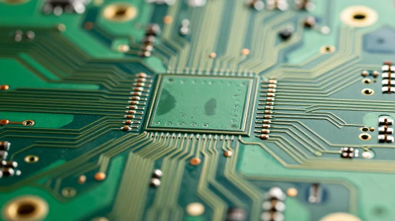
In commercial drone flight controllers, selecting the appropriate copper weight is a critical balancing act between electrical performance and mechanical reliability. While heavier copper is essential for managing the high current demands of brushless motor ESCs and power distribution systems, excessive copper thickness increases the PCB's stiffness profile, making it more prone to fatigue cracking and delamination under constant high-frequency vibration.
Strategic Trace Design and Material Compatibility
To mitigate failure modes, engineers must prioritize trace geometry over brute-force copper thickness. Utilizing wider, thinner traces can often achieve the same current capacity as narrow, thick traces while offering superior flexibility under stress. Furthermore, incorporating teardrop pads at trace intersections reduces stress concentration points, significantly lowering the risk of copper-to-substrate separation during prolonged thermal and mechanical cycling.
| Copper Strategy | Advantage | Risk Factor |
|---|---|---|
| Standard (1 oz) | High Flexibility | Thermal bottlenecks |
| Heavy Copper (2-3 oz) | High Current Density | Delamination under G-load |
| Balanced Multi-layer | Optimized Impedance | Increased PCB Thickness |
Addressing Common Copper Integrity Challenges
- How does copper thickness affect vibration resistance?
Thicker copper adds mass and rigidity to the PCB surface. Under vibration, this rigidity creates localized stress risers that can cause the copper foil to separate from the substrate, specifically at pad interfaces. - What role do teardrops play in trace integrity?
Teardrops provide a structural transition between a narrow trace and a wide pad, distributing mechanical force over a larger surface area rather than a single junction point, thus preventing trace cracking. - Is internal layer copper safer than surface copper?
Internal layers are physically constrained by the dielectric material on both sides, making them inherently more resistant to delamination than external layers, which should be reserved for signal paths with lower current requirements.
Surface Finishes and Solder Joint Reliability
Surface Finishes and Solder Joint Reliability
In the context of flight controllers subjected to continuous mechanical stress, the surface finish acts as the metallurgical interface between the component and the PCB. A finish that is susceptible to brittle intermetallic compound (IMC) formation or poor wetting can lead to fatigue-induced fractures when drones undergo rapid maneuvers or high-G accelerations.
| Surface Finish | Vibration Performance | Reliability Profile |
|---|---|---|
| ENIG | Moderate | Excellent flatness for BGAs but susceptible to black pad syndrome. |
| HASL (Lead-Free) | Low | Poor planarity leads to uneven solder joint stress distributions. |
| OSP | High | Provides a flatter, more ductile interface, though limited shelf life. |
| ENEPIG | Very High | Superior structural integrity; best for high-reliability aerospace apps. |
Comparison of Industry Standard Finishes
For commercial drone flight controllers, the goal is to maximize the fatigue life of the solder joints. While ENIG (Electroless Nickel Immersion Gold) is common, the underlying nickel layer can become brittle over time. If the drone is prone to high-frequency harmonic vibrations, transitioning to ENEPIG (Electroless Nickel Electroless Palladium Immersion Gold) or Organic Solderability Preservative (OSP) is recommended. OSP, by nature, offers a direct copper-to-solder interface that is inherently more ductile than nickel-based alternatives, effectively absorbing mechanical shock rather than fracturing.
- Why is HASL unsuitable for high-vibration applications?
HASL creates an uneven, non-planar surface finish that leads to inconsistent solder fillet shapes, which create stress concentrators under vibration. - Does ENIG cause solder joint failure?
ENIG can suffer from 'black pad' syndrome and brittle intermetallic layers, which may crack during prolonged thermal and mechanical cycling typical of flight operations. - What is the primary benefit of OSP in drone flight controllers?
OSP provides a coplanar surface and a more ductile copper-solder joint, offering better resilience against the mechanical fatigue induced by drone motors.
Advanced Mechanical Mounting and Vibration Damping
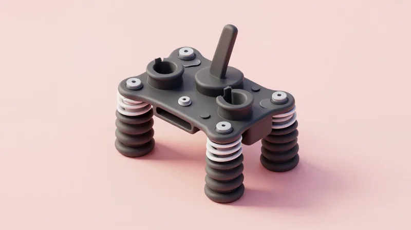
In commercial drone flight controllers, PCB reliability is not solely dependent on the substrate material or solder joint integrity; it is fundamentally tied to how the board is mechanically isolated from high-frequency motor vibrations and low-frequency aerodynamic oscillations. Failing to implement robust decoupling strategies can lead to 'gyro-noise' injection, where structural vibrations manifest as electronic signals, potentially causing catastrophic flight instability.
Mechanical Decoupling Strategies
The primary objective is to interrupt the mechanical transmission path between the drone frame and the flight controller. For high-reliability applications, rigid mounting must be avoided. Instead, engineers should specify PCB mounting points that utilize standoff materials with varying shore hardness to achieve a natural resonant frequency significantly lower than the drone's operational motor frequencies.
| Isolation Method | Damping Effectiveness | Mechanical Stability | Best Application |
|---|---|---|---|
| Silicone Grommets | High | Moderate | General quadcopter flight controllers |
| Wire-Rope Isolators | Very High | Low | Heavy-lift sensor arrays |
| Polyamide/Nylon Spacers | Low | Very High | Fixed-wing avionics |
| Gel-Damping Pads | Moderate | High | Component-level vibration suppression |
Vibration Damping Best Practices
- How does silicone hardness impact vibration dampening?
Lower shore hardness provides superior high-frequency attenuation but reduces structural rigidity, potentially causing the PCB to shift during aggressive maneuvers. A shore 40A to 60A rating is typically the 'sweet spot' for commercial drones. - Why should cable stress relief be integrated into the mounting design?
Vibration-damped PCBs fail prematurely if cables are tight, as these act as mechanical 'bridges' that bypass the isolators. Always use flexible, lightweight silicone-insulated wiring with slack loops to prevent vibration transmission through the interconnects. - Is rigid mounting ever preferred?
Only if the flight controller firmware incorporates advanced active noise-canceling algorithms and the chassis exhibits extremely high stiffness. In almost all other cases, active isolation is superior to rigid mounting for sensor health.
Ultimately, the selection of the mounting system must be verified through modal analysis. A PCB that is too compliant might oscillate during high-G turns, while one that is too rigid will fatigue solder joints prematurely due to harmonic stress. By combining silicone damping with intelligent cable routing, manufacturers can significantly extend the operational life of mission-critical flight electronics.
Rigid-Flex vs. Traditional Rigid PCBs
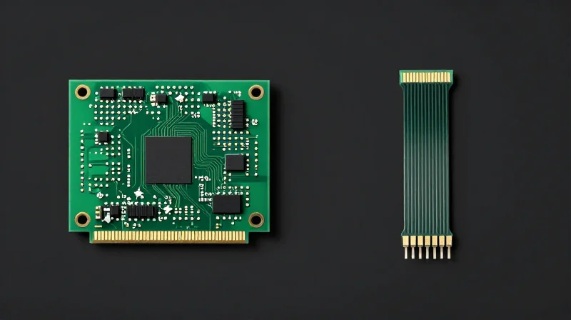
Rigid-Flex vs. Traditional Rigid PCBs in Flight Controllers
In compact, high-performance drone architectures, connector-to-PCB interfaces are frequently the weakest mechanical links. While traditional rigid PCBs paired with board-to-board connectors are standard, they are susceptible to fretting corrosion and contact intermittent failure under constant high-frequency vibration. Rigid-flex circuits eliminate these mechanical points of failure by replacing bulky connectors and heavy wiring harnesses with integrated, monolithic flexible polyimide interconnects.
Comparative Analysis: Vibration Resistance and Reliability
| Feature | Traditional Rigid PCB | Rigid-Flex PCB |
|---|---|---|
| Mechanical Interconnects | High (Connectors/Cables) | Low (Integrated Circuits) |
| Vibration Fatigue | Risk of Connector Fretting | Superior (Monolithic) |
| Space Optimization | Low Efficiency | High Efficiency |
| Manufacturing Cost | Lower | Higher |
| Assembly Complexity | High (Manual cabling) | Low (Single assembly) |
Strategic Implementation Guidelines
- When should you switch to rigid-flex?
Consider rigid-flex when your drone design suffers from intermittent signal loss due to vibration-induced connector micro-motion or when space constraints prevent the use of robust mechanical mounting systems. - What are the primary reliability gains?
The transition to rigid-flex removes the need for solder joints at connector pins, which are prone to cracking. The flexible regions provide inherent dampening, absorbing energy that would otherwise stress electronic components. - Are there drawbacks to high-vibration applications?
Yes, cost and design lead times. Additionally, the flexible regions must be carefully managed to prevent resonant frequencies that could lead to material fatigue; this requires precise stack-up design and mechanical strain relief in the flexible transitions.
For flight controllers subjected to extreme, sustained operational vibrations, the monolithic nature of rigid-flex technology offers a significant step-up in reliability. By reducing the parts count and eliminating mechanical friction points, engineers can create a more predictable and vibration-resistant electronic environment.
Conformal Coating and Environmental Protection
Selecting the Optimal Coating Chemistry
Choosing the right conformal coating requires balancing dielectric performance with mechanical elasticity, as rigid coatings can crack under the constant micro-vibrations inherent in drone flight. For high-reliability applications, polyurethane or silicone-based materials are preferred over acrylics due to their superior resistance to thermal cycling and moisture ingress.
| Coating Type | Vibration Resistance | Moisture Protection | Ease of Rework |
|---|---|---|---|
| Silicone | Excellent | High | Difficult |
| Polyurethane | Good | Excellent | Moderate |
| Acrylic | Moderate | Moderate | Easy |
Application Methodologies for Flight Controllers
The method of application—whether manual spraying, brush coating, or automated selective coating—directly impacts the long-term reliability of sensitive components. Automated selective coating is recommended for commercial-grade flight controllers to ensure uniform thickness across high-density component arrays, preventing uneven stress concentrations that can lead to solder joint failure during extreme maneuverability.
Common Concerns and Best Practices
- How does coating thickness affect thermal management?
Excessive coating thickness acts as an insulator, potentially causing high-power components like MOSFETs to overheat during intense flight operations. - Should connectors be coated?
No, connectors should be masked or protected using peelable masks before application, as coating migration into contact pins introduces high contact resistance or intermittent signals. - What is the impact of conformal coating on vibration damping?
Elastic coatings can act as a secondary vibration dampener for small surface-mount components, reducing the mechanical stress transferred to the solder fillets during rapid motor RPM changes.
Compliance and Testing Protocols
Establishing Compliance Standards
For commercial UAV flight controllers, selecting PCBs based on IPC standards is the baseline for industrial-grade reliability. Boards must conform to IPC-6012 Class 3, which mandates stringent requirements for hole wall copper thickness, annular ring integrity, and plating quality. In high-vibration environments, compliance with IPC-9701 (Solder Attachment Reliability) is also critical to ensure interconnects can withstand thermal and mechanical cycling without propagating cracks.
Essential Reliability Testing Protocols
Validating the structural integrity of a PCB requires simulating the harsh operational reality of a drone in flight. The following protocols are industry best practices for mission-critical hardware.
| Test Method | Purpose | Typical Specification |
|---|---|---|
| Random Vibration | Simulates broad-spectrum drone motor frequency | MIL-STD-810H, Method 514.8 |
| Mechanical Shock | Validates resistance to hard landings | MIL-STD-810H, Method 516.8 |
| Thermal Cycling | Tests solder fatigue under expansion/contraction | IPC-9701 (TCT) |
Frequently Asked Questions
- Why is IPC Class 3 preferred over Class 2 for flight controllers?
Class 3 provides higher manufacturing tolerances and stricter inspection criteria, which are necessary for systems where continuous performance is life-critical. - How does vibration testing impact board design?
Vibration testing often forces changes to layout, such as relocating heavy components away from board centers or adding additional mounting holes to increase stiffness. - Is functional testing enough to guarantee reliability?
No; functional testing only confirms current operation. Environmental stress screening (ESS) is required to detect latent manufacturing defects that vibration will exacerbate over time.
Selecting the right PCB architecture is the foundation of a reliable drone flight controller. By prioritizing high-Tg materials, robust copper integrity, and vibration-dampened assembly, you ensure that your hardware excels even under the most demanding flight conditions. Ready to elevate your hardware reliability? Contact our engineering team today to discuss your next mission-critical project.
