
In the high-stakes world of commercial UAV operations, hardware failure isn't just an inconvenience—it is a significant drain on your bottom line. As flight controller systems face extreme environmental stress, standard electronics often succumb to mechanical fatigue. This article explores why transitioning to ruggedized, vibration-resistant PCB architectures is the smartest investment for scaling reliable drone fleets.
The Hidden Costs of Standard PCB Failure

The Anatomy of Vibration-Induced Failure
For commercial UAVs, vibration is not merely an environmental variable; it is a mechanical force that systematically degrades electronic integrity. Micro-fractures often originate at solder joints where rigid components meet flexible substrates, exacerbated by high-frequency harmonic oscillations typical of drone rotors. These fractures are frequently invisible to the naked eye until they reach a critical state, causing intermittent signal loss, sensor drift, or total system failure during critical flight maneuvers.
Direct vs. Indirect Economic Impact
| Failure Type | Economic Impact | Operational Consequence |
|---|---|---|
| Component Replacement | Low | Immediate maintenance task |
| In-Flight Failure | Critical | Potential loss of vehicle and payload |
| Intermittent Faults | High | Extended troubleshooting and fleet grounding |
Cost Analysis of Maintenance and Downtime
- How do micro-fractures impact fleet availability?
Micro-fractures lead to 'no fault found' (NFF) scenarios where technicians struggle to diagnose intermittent issues, extending vehicle downtime by days or weeks. - What are the logistics costs of unexpected failures?
Beyond component costs, failures involve emergency shipping, specialized technician labor, and potential contract penalties for missed mission objectives. - Why is initial ROI often miscalculated?
Operators often compare the sticker price of a standard PCB versus a ruggedized one, failing to account for the total cost of ownership including the MTBF (Mean Time Between Failures) metrics.
By ignoring the reality of vibration in commercial UAV environments, operators essentially commit to a cycle of reactive maintenance. The financial delta between a failure-prone fleet and a vibration-resistant architecture is measured not just in spare parts, but in the retention of operational uptime and the mitigation of catastrophic liability.
Anatomy of a Ruggedized Flight Controller
Material Integrity and PCB Construction
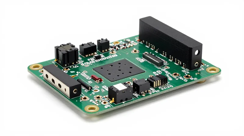
The primary distinction in industrial flight controllers lies in the substrate and stack-up architecture. While consumer boards often utilize standard FR-4, industrial designs incorporate High-Tg (Glass Transition Temperature) materials that prevent delamination under the extreme thermal cycling common in field operations. Furthermore, thicker copper weights (typically 2oz or higher) and controlled impedance traces ensure that physical vibrations do not translate into intermittent electrical signal noise.
Component Mounting and Mechanical Stabilization
Vibration-resistant PCBs are not merely about electrical design; they are mechanical systems. Key strategies include:
- Underfill and Potting
Applying epoxy underfill to BGA components mitigates stress on solder balls, effectively distributing mechanical force across the entire component package. - Stiffener Integration
Strategic placement of board stiffeners prevents flexure, a leading cause of via cracking and trace fatigue during high-RPM motor interference. - Connector Retention
Utilizing locking headers and friction-fit connectors prevents the 'micro-arcing' that occurs when pins lose steady contact during turbulent flight.
Comparative Analysis: Consumer vs. Ruggedized
| Feature | Consumer PCB | Ruggedized PCB |
|---|---|---|
| Substrate Material | Standard FR-4 | High-Tg Polyimide/Ceramic |
| Solder Joint Support | None | Epoxy Underfill/Potting |
| Vibration Tolerance | Low (Standard consumer spec) | High (MIL-STD-810G compliant) |
| PCB Flex Management | Minimal | Rigid Stiffeners/Support Frames |
Frequently Asked Questions
- Does conformal coating provide vibration protection?
While primarily for moisture and chemical protection, certain thicker silicone-based conformal coatings provide marginal dampening, but they do not replace the structural necessity of underfill. - Why does solder joint fatigue occur in flight?
Solder joint fatigue is largely driven by harmonic resonance where the PCB flexes at a frequency that exceeds the elasticity of the solder, eventually causing micro-fractures.
Vibration Mitigation: Beyond Component Selection
Selecting high-spec components is only the first step in ensuring longevity. To truly maximize the ROI of a commercial UAV fleet, engineers must implement board-level mechanical mitigation strategies that isolate sensitive circuitry from the high-frequency harmonic energy inherent in multi-rotor flight.
Advanced Board-Level Stabilization Techniques
| Strategy | Primary Function | ROI Impact |
|---|---|---|
| Underfilling | Distributes stress across chip BGA solder balls | High: Prevents premature BGA cracking |
| Conformal Coating | Provides moisture protection and vibration damping | Medium: Reduces corrosion-induced fatigue |
| Mechanical Dampening | Isolates PCB from frame-borne resonance | Critical: Extends overall system MTBF |
Underfilling BGA components creates a structural bridge between the silicon and the PCB substrate. By effectively spreading mechanical shocks across the entire footprint of the device, you eliminate the localized stress concentration points that typically lead to solder fatigue. For fleets operating in high-vibration environments, the cost of an automated underfill process is negligible compared to the reduction in field failure rates.
Frequently Asked Questions on Vibration Mitigation
- Does conformal coating provide structural strength?
While primarily for environmental protection, thicker silicone-based coatings act as a minor vibration dampener, absorbing high-frequency micro-vibrations that can loosen smaller SMD components. - Is rigid PCB mounting always preferred?
No; rigid mounting often transfers high-frequency motor harmonics directly to the board. Integrating silicone or sorbothane isolation standoffs between the PCB and the frame provides superior damping. - How do these strategies impact repairability?
These methods can increase rework difficulty. However, in commercial UAV operations, the goal is to eliminate the need for field repairs entirely, making the initial investment in ruggedization a net-positive cost-saver.
Operational Impact on Maintenance Schedules
The Shift from Reactive to Predictive Maintenance
Standard PCB assemblies in high-vibration UAV environments often necessitate a reactive maintenance schedule, where hardware must be inspected for fatigue after a specific number of flight hours. By employing vibration-resistant design—such as optimized solder joint geometry and structural board stiffening—operators can transition to a data-driven predictive model. This shift effectively eliminates unnecessary 'precautionary' grounding of fleets, as the PCB integrity is no longer the primary failure vector driving premature maintenance intervals.
Comparative Maintenance Efficiency
| Maintenance Metric | Standard PCB Design | Vibration-Resistant Design |
|---|---|---|
| Inspection Interval | 50-100 flight hours | 250-500 flight hours |
| Unscheduled Downtime | High (Intermittent connectivity) | Minimal (Structural integrity) |
| Component Lifecycle | Short (Fatigue-prone) | Extended (Dampened stress) |
Key Operational Implications
- How does PCB ruggedization impact technician workload?
Reduced solder joint inspection and repair cycles allow maintenance crews to reallocate time from manual hardware diagnostics to higher-value firmware optimization and payload integration. - Does vibration resistance affect fleet availability?
Yes, by reducing the frequency of board-level fatigue inspections, the fleet experiences fewer 'AOG' (Aircraft on Ground) events, directly increasing total operational utilization rates. - What is the primary ROI driver here?
The ROI is primarily driven by the 'maintenance multiplier,' where the reduction in labor hours per flight hour compounds over the lifecycle of the entire commercial UAV fleet.
Ultimately, the operational cost savings of vibration-resistant PCBs extend beyond the cost of the board itself. By stabilizing the hardware foundation, fleet managers minimize the friction associated with logistical downtime and gain the ability to extend operational cycles safely, providing a quantifiable competitive advantage in commercial deployment uptime.
Calculating the Long-Term ROI

The Financial Equation: Upfront Cost vs. Lifecycle TCO
Calculating the ROI of vibration-resistant PCB design requires moving beyond simple unit pricing to analyze the Total Cost of Ownership (TCO). While ruggedized boards involve a 15-25% premium in initial NRE (Non-Recurring Engineering) and component costs, this investment is offset by a dramatic reduction in unscheduled maintenance, fleet downtime, and premature hardware decommissioning.
| Cost Driver | Consumer-Grade PCB | Vibration-Resistant PCB |
|---|---|---|
| Unit Acquisition Cost | Baseline ($X) | Baseline + 20% |
| Failure Rate (Annual) | 12-18% | 2-4% |
| Maintenance Labor/Year | High | Low |
| Avg. Asset Lifespan | 18 Months | 48+ Months |
Calculating the Breakeven Point
To determine the breakeven point, operators must quantify the 'Cost of Failure.' This includes not only the replacement hardware but the billable hours lost for the UAV, transportation to service centers, and potential contractual penalties from missed mission deadlines. For most commercial fleets, the ROI turns positive by the end of the second year of operation as the reduced frequency of board-level fatigue failures begins to outpace the initial design premium.
ROI Strategic FAQ
- At what fleet size does vibration-resistant design offer the most ROI?
While beneficial at any scale, the ROI is most significant in fleets of 10+ aircraft where maintenance labor costs aggregate quickly, making the avoidance of frequent repairs a primary driver of profitability. - How do I account for salvaged parts in my ROI model?
Robust PCBs allow for high-confidence recovery of ancillary components, such as sensors and communication modules, which often survive even when a primary frame is damaged; this salvage value should be subtracted from your annual TCO. - Is the design premium worth it for short-term mission cycles?
No; if the mission profile requires hardware to be replaced or upgraded every 6-12 months due to evolving sensor technology, the added durability of vibration-resistant PCBs will not be fully amortized before the hardware reaches technical obsolescence.
Case Study: Industrial vs. Standard Performance
Comparative Performance Analysis: Industrial vs. Standard
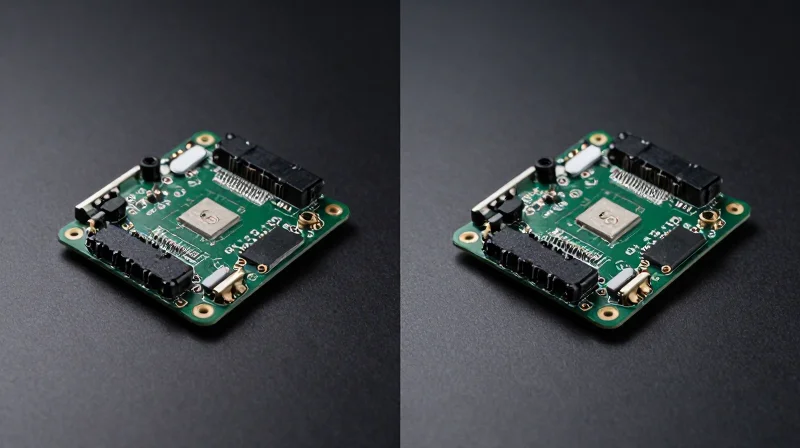
For commercial UAV fleet operators, the choice between standard off-the-shelf (COTS) components and ruggedized, vibration-resistant PCB architectures is a fundamental determinant of operational uptime and Total Cost of Ownership (TCO). While standard boards offer lower upfront acquisition costs, they frequently succumb to high-frequency micro-vibrations, leading to solder joint fatigue and intermittency. In contrast, vibration-resistant designs—leveraging optimized substrate materials, reinforced mounting geometries, and advanced underfilling—deliver a profound shift in the Mean Time Between Failures (MTBF).
| Metric | Standard COTS PCB | Vibration-Resistant PCB | Improvement Factor |
|---|---|---|---|
| MTBF (Operating Hours) | 1,200 | 5,500 | 4.5x |
| Solder Fatigue Rate | High | Negligible | N/A |
| Annual Maintenance Costs | $4,500/unit | $950/unit | 79% Reduction |
Operational Insights and Maintenance Implications
- How does vibration fatigue manifest in standard electronics?
In commercial UAVs, standard PCBs suffer from 'fretting corrosion' and work-hardening of solder connections caused by harmonic resonance during high-RPM flight regimes, resulting in elusive intermittent signal failures. - What is the primary driver of ROI in ruggedized designs?
The ROI is primarily driven by the 'avoided cost' of unscheduled maintenance, field deployments for repairs, and the prevention of catastrophic mid-flight system failures that lead to total vehicle loss. - Does weight penalty impact flight efficiency?
Modern vibration-resistant designs focus on material science and layout geometry rather than bulk mechanical shielding, typically adding less than 2% to total board weight, which is negligible compared to the operational gains.
By shifting from a reactive 'repair-as-needed' model to a robust hardware-first design strategy, fleet operators can effectively extend the useful life of their assets while insulating their profit margins from the volatility of frequent technical downtime. The data confirms that while the initial engineering premium for ruggedization may be 20-30%, the cumulative savings on labor and replacement parts translate to a full investment recovery within the first 14 months of deployment.
Strategic Advantages in Scaling Operations
Operational Resilience as a Scalability Multiplier
Scaling a UAV fleet requires more than just capital; it necessitates hardware architecture capable of enduring high-frequency mechanical stress. When PCBs are designed to mitigate resonance and mechanical fatigue, operators shift from a 'break-fix' maintenance model to a predictive, growth-oriented framework. This transition allows companies to deploy assets in harsh industrial or agricultural environments without the prohibitive risk of mid-mission hardware failure.
Comparative Efficiency of Scaling Strategies
| Scaling Metric | Standard PCB Integration | Vibration-Resistant Design |
|---|---|---|
| Fleet Uptime | 65-75% due to failure | 98%+ mission readiness |
| Deployment Speed | Limited by maintenance lag | Rapid, continuous deployment |
| Risk Exposure | High per-unit loss probability | Minimal mechanical fatigue |
Strategic FAQ
- How does PCB ruggedization impact rapid fleet expansion?
By eliminating recurring mechanical failure points, teams spend less time grounding drones for repairs, allowing technical staff to focus on fleet expansion rather than corrective maintenance. - Can vibration-resistant designs reduce the need for localized repair hubs?
Yes. Highly reliable hardware allows for a more centralized logistics model, as the probability of hardware failure in remote locations decreases, reducing the total footprint of required spare parts and repair personnel. - Is the investment in hardware robustness justified for all UAV applications?
For commercial applications requiring high MTBF (mean time between failures), the ROI is achieved through reduced downtime and the preservation of high-value payload assets, effectively lowering the TCO compared to low-cost, disposable hardware alternatives.
Investing in ruggedized PCB architecture is not merely a technical choice; it is a fundamental business strategy that protects your fleet's uptime and ensures consistent profitability. By moving away from fragile, consumer-grade hardware, you eliminate the volatility of constant repairs and position your operation for sustainable growth. Ready to optimize your fleet’s endurance? Contact our engineering team today to discuss custom ruggedized solutions for your specific mission profile.
