
The demand for high-torque electric mobility is skyrocketing, but our current electronic hardware is hitting a thermal wall. As manufacturers pack more power into smaller motor housings, traditional fiberglass-reinforced boards are struggling to dissipate the heat generated by modern power electronics. This shift in performance requirements necessitates a transition to high-efficiency thermal substrates. In this article, we analyze why aluminum-core PCBs are becoming the industry gold standard for sustainable and reliable e-bike architecture.
The Thermal Limitations of Standard FR4
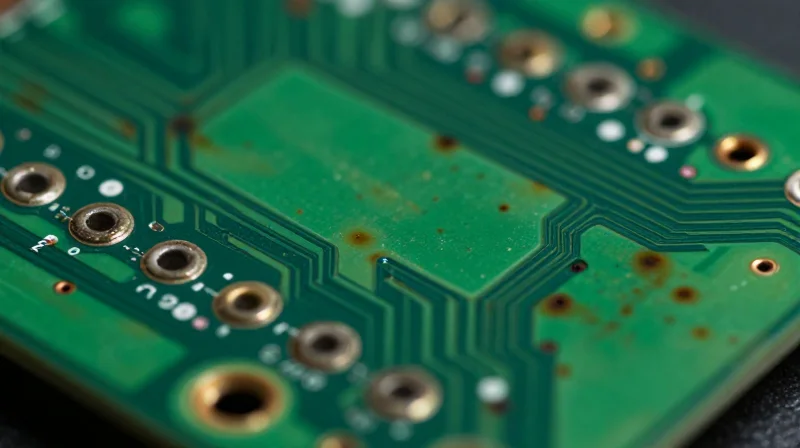
The Thermal bottleneck of FR4 Architecture
FR4, or Flame Retardant 4, is a composite material consisting of woven fiberglass cloth impregnated with epoxy resin. While cost-effective and structurally sound for consumer electronics, it is inherently a thermal insulator. In the context of e-bike power electronics, where high-current MOSFETs generate significant heat, FR4 lacks the requisite thermal conductivity to dissipate energy effectively. This leads to localized hotspots that shorten the lifespan of semiconductor components and threaten overall system reliability.
Comparative Thermal Conductivity
| Material Type | Thermal Conductivity (W/mK) | Application Suitability |
|---|---|---|
| Standard FR4 | 0.25 | Low-power control logic |
| Aluminum Metal Core | 1.0 - 3.0 | High-power MOSFET stages |
| Copper Core PCB | 380.0 | Ultra-high current applications |
Frequently Asked Questions Regarding Thermal Limits
- Why does FR4 fail in high-current e-bike controllers?
The low thermal conductivity of epoxy resin causes heat to accumulate around the base of switching components, leading to thermal runaway or rapid aging of the board substrate. - Can thick copper plating solve FR4 thermal issues?
While increasing copper weight helps distribute heat laterally, it does not solve the fundamental problem of vertical heat dissipation through the insulating fiberglass core. - What is the primary consequence of exceeding thermal limits?
Beyond simple hardware failure, consistent overheating leads to delamination of copper traces and the glass transition temperature (Tg) being exceeded, rendering the PCB mechanically unstable.
Anatomy of an Aluminum-Core PCB
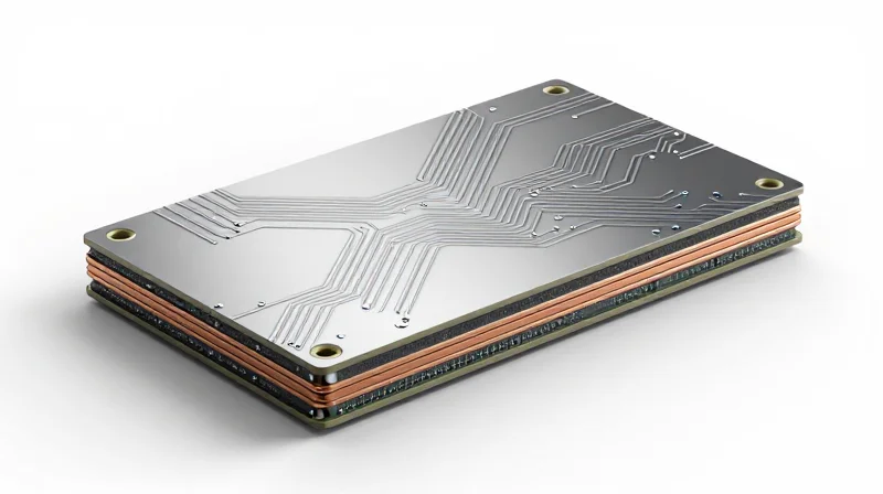
Structural Architecture of Aluminum-Core PCBs
Unlike standard FR4 boards that rely on glass-reinforced epoxy resin, aluminum-core PCBs—often referred to as Metal Core Printed Circuit Boards (MCPCBs)—utilize a composite architecture engineered for extreme thermal management. The structure is typically a four-layer stack: the copper circuit layer, a high-thermal-conductivity dielectric layer, the aluminum metal base, and a protective solder mask.
The Role of the Dielectric and Metal Base
The critical differentiator is the dielectric layer. In an e-bike motor controller, heat must migrate rapidly from surface-mount components (like MOSFETs) to the chassis. In FR4, the resin acts as an insulator, trapping heat. In an MCPCB, the dielectric is a ceramic-filled polymer designed to be as thin as possible while maintaining electrical isolation, ensuring heat passes directly into the aluminum base plate. The aluminum acts as an integrated heatsink, spreading thermal energy across a wider surface area to be dissipated through convection or conduction.
| Feature | FR4 PCB | Aluminum MCPCB |
|---|---|---|
| Thermal Conductivity | Low (0.2–0.5 W/mK) | High (1.0–5.0+ W/mK) |
| Base Material | Fiberglass/Epoxy | Aluminum Alloy |
| Heat Dissipation | Via-heavy (often inefficient) | Direct conduction through base |
| Mechanical Rigidity | Flexible/Standard | High Structural Stability |
Frequently Asked Questions
- Can you use vias in an aluminum PCB for better cooling?
While possible, it is rarely necessary. The primary thermal path in an MCPCB is vertically through the thin dielectric layer directly into the aluminum base, bypassing the need for complex via stitching common in FR4 designs. - Does the aluminum base affect the circuit's electrical performance?
The metal base is electrically isolated from the circuit layer by the dielectric material. However, designers must ensure the dielectric maintains its breakdown voltage integrity under high-current spikes common in e-bike controllers.
Heat Dissipation Efficiency: A Comparative Metric
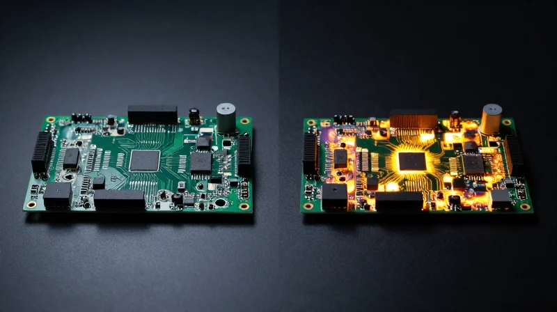
Thermal Conductivity: The Comparative Performance Gap
The primary differentiator between FR4 and Aluminum PCBs lies in their thermal conductivity coefficients. While standard FR4 acts as an effective thermal insulator—leading to heat entrapment in high-current e-bike motor controllers—Aluminum-Core PCBs (MCPCBs) function as highly efficient heat sinks. The dielectric layer in an MCPCB is specifically engineered to minimize thermal resistance, facilitating rapid heat transfer from critical power components like MOSFETs directly to the metal substrate.
| Material Type | Thermal Conductivity (W/m·K) | Heat Dissipation Capacity |
|---|---|---|
| Standard FR4 | 0.25 - 0.35 | Poor (Insulative) |
| Aluminum-Core PCB | 1.0 - 3.0 | Excellent (Conductive) |
Heat Spreading Dynamics in E-Bike Controllers
In e-bike power electronics, localized hotspots are the leading cause of component degradation. FR4 boards require bulky external heatsinks to mitigate these hotspots, significantly increasing the weight and volume of the controller chassis. Conversely, Aluminum PCBs distribute heat laterally across the entire metal backing plate, which allows for smaller footprints without sacrificing the power density required for high-torque climbing or sustained high-speed operation.
Thermal Management FAQ
- Why does FR4 fail under high current?
FR4 has very low thermal conductivity, essentially trapping heat produced by power MOSFETs, leading to junction temperature spikes and eventual board delamination. - Does the dielectric layer reduce efficiency?
While the dielectric layer does introduce some thermal resistance, it is intentionally kept as thin as possible (often 50-150 microns) to ensure the majority of heat flux reaches the aluminum base quickly. - Can aluminum boards eliminate external heat sinks?
In many e-bike designs, the aluminum board acts as part of the mechanical chassis, effectively replacing bulky external sinks with a unified, thermally efficient structural design.
Longevity and Reliability in High-Torque Environments
Engineering Durability for High-Torque Cycles
In high-torque e-bike applications, the power electronics board acts as a structural component as much as an electrical one. Standard FR4 is inherently flexible, often leading to micro-cracking in solder joints during the repetitive mechanical stresses induced by aggressive terrain and high-torque motor bursts. Aluminum-core PCBs provide a rigid, metal-backed substrate that prevents board flex, directly increasing the longevity of surface-mount devices (SMDs) and sensitive power FETs.
Comparative Reliability Metrics
| Failure Factor | FR4 Performance | Aluminum PCB Performance |
|---|---|---|
| Thermal Expansion (CTE) | High (Mismatch with copper) | Low (Matched to components) |
| Vibration Resistance | Poor (Board flexing) | Excellent (High rigidity) |
| Solder Joint Integrity | Prone to fracture | High resilience |
| Operating Lifespan | Shortened by thermal cycling | Extended by heat dissipation |
Frequently Asked Questions
- How does an aluminum base prevent component failure?
The metal core acts as a heat sink and a structural support, minimizing the mechanical flexure that causes solder joints to crack during high-vibration off-road usage. - Is the rigidity of an aluminum PCB always beneficial?
While superior for vibration, the rigidity requires precise chassis mounting to ensure that external frame stresses are not transferred directly into the board, which could lead to physical deformation. - Can FR4 be reinforced to match aluminum reliability?
While thicker copper planes and conformal coatings help, they cannot match the inherent thermal-mechanical stability provided by the metallic interface of an MCPCB.
Cost-Benefit Analysis for Manufacturers
The transition from standard FR4 to aluminum-core PCBs represents a strategic shift from component-level savings to system-level efficiency. While aluminum substrates command a higher per-unit cost due to material complexity and manufacturing constraints, the economic viability of this choice is anchored in the radical simplification of thermal management architectures.
Economic Trade-offs: Initial Investment vs. Operational Value
| Cost Factor | Standard FR4 | Aluminum PCB | Impact |
|---|---|---|---|
| Material Cost | Low | High | Aluminum is 2x-3x higher |
| Cooling Complexity | High | Low | Aluminum reduces heatsink size |
| Warranty Claims | High | Low | Aluminum improves reliability |
| System Weight | Baseline | Lower | Weight savings in e-bikes |
In e-bike motor controllers, heat is the primary enemy of lifespan. Using FR4 often requires large aluminum heatsinks, thermal pads, and complex mounting hardware to move heat away from MOSFETs. Aluminum PCBs act as the heatsink itself, allowing for a more compact design that reduces assembly labor and total bill of materials (BOM) weight, which is a critical selling point for premium e-mobility products.
Long-term Reliability and Warranty Savings
- How does aluminum impact warranty costs?
By maintaining lower junction temperatures, aluminum PCBs significantly reduce the rate of semiconductor degradation, directly correlating to a lower return-to-service rate under warranty. - Can we recover the higher board costs?
Yes, through the removal of external mechanical cooling structures and a reduction in the physical housing dimensions, the total system cost often achieves parity or net savings in production. - Is the transition viable for entry-level models?
Current trends suggest aluminum PCBs are most effective in mid-to-high torque applications where thermal stress is constant; entry-level units may still benefit more from cost-optimized FR4.
For manufacturers, the decision rests on the 'cost of failure.' The expense of a single recall or field-failure in high-torque e-bike systems far exceeds the unit price delta of switching to an aluminum substrate. By prioritizing high-thermal-conductivity materials, OEMs create a more robust product that sustains peak torque delivery over the entirety of its lifecycle, ultimately enhancing brand equity and reducing churn.
Design Challenges and Industry Best Practices
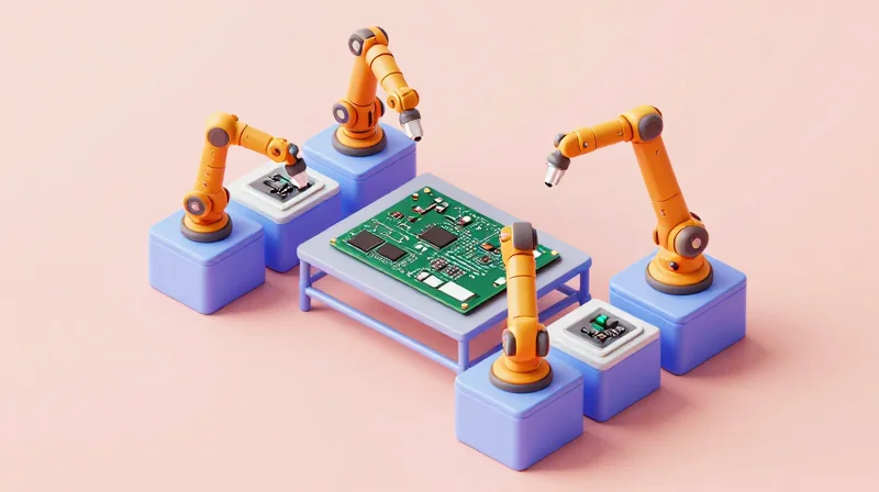
Design and Manufacturing Hurdles
Designing with Aluminum PCBs requires a fundamental shift from standard FR4 workflows. Because the metal core is conductive, standard drilling processes can cause burrs or short circuits if the dielectric layer is compromised. Furthermore, thermal interface material (TIM) selection becomes the primary bottleneck; if the interface between the metal core and the chassis is inconsistent, the thermal advantage of the substrate is rendered ineffective.
| Challenge | FR4 Impact | Aluminum PCB Strategy |
|---|---|---|
| Machining | Standard routing/punching | Requires specialized carbide tools |
| Thermal Coupling | Air gap sensitive | TIM precision is mandatory |
| Electrical Isolation | Inherently isolated | Edge routing to avoid shorts |
Industry Best Practices
- Edge Treatment
Always perform edge routing or filing to remove metal burrs that may bridge the dielectric layer and cause shorts to the casing. - Optimized TIM Application
Prioritize high-performance phase-change materials or thermally conductive pads to ensure uniform contact between the metal base and the e-bike frame. - Via Placement
Avoid plated-through holes (PTH) that touch the metal base unless specifically designed for electrical ground connection through an isolated barrier.
Future-Proofing E-Bike Power Systems
To future-proof power systems, designers should adopt a holistic approach by treating the aluminum PCB not just as a circuit carrier, but as a structural thermal component. By aligning the PCB mounting points with the e-bike’s structural extrusions, manufacturers can maximize heat sinking capabilities while reducing the reliance on secondary active cooling components, ultimately leading to lighter and more resilient motor controller architectures.
Future Trends in Power Electronic Architecture

The Shift Toward Integrated Thermal Management
As e-bike motors evolve toward higher torque and compact form factors, the power electronic architecture must shed heat more efficiently than ever before. The future trend points away from standalone cooling fans and heat sinks, favoring integrated thermal solutions where the PCB itself acts as the primary heat dissipation conduit. Aluminum PCBs are becoming the industry standard for high-wattage motor controllers, as they effectively bridge the gap between cost-efficiency and high thermal conductivity.
Comparative Outlook: Substrate Material Evolution
| Feature | Standard FR4 | Aluminum PCB | Ceramic (IMS/DBC) |
|---|---|---|---|
| Thermal Conductivity | Poor | Moderate/High | Excellent |
| Cost Efficiency | High | Moderate | Low |
| Current Density | Low | High | Ultra-High |
| Application | Logic/Controls | Power Modules | High-Performance Inverters |
Key Emerging Trends
- Increased Integration Density
Miniaturization is forcing components closer together, necessitating thermally conductive substrates to prevent localized hotspots that traditional FR4 cannot manage. - Shift to Wide Bandgap Semiconductors
The adoption of GaN and SiC semiconductors requires substrates capable of handling rapid switching speeds and high temperatures, where metal-core boards provide superior dielectric reliability. - System-on-Substrate Concepts
Engineers are increasingly moving toward embedding power components directly into the substrate to minimize parasitic inductance, a process that favors the rigid, heat-conductive nature of aluminum.
Future Outlook for E-Bike Architecture
The next decade will see a bifurcation in e-bike electronics. Standard FR4 will remain reserved for human-machine interfaces and low-power telemetry, while the propulsion system—specifically motor controllers and battery management systems—will almost exclusively utilize metal-core or ceramic-based architectures. Manufacturers who prioritize the integration of these high-performance materials today will gain a significant competitive advantage in power density and overall vehicle reliability.
Transitioning to metal-core PCB technology is no longer an optional luxury but a necessity for e-bike manufacturers aiming to lead in performance and reliability. By prioritizing superior thermal management now, your design team can ensure long-term hardware success. Ready to optimize your motor electronics? Contact our engineering team today for a custom evaluation of your PCB thermal strategy.
