
As the e-bike market accelerates, the pressure on motor controllers to perform under intense thermal stress is at an all-time high. Manufacturers are finding that traditional substrate choices are becoming a bottleneck for reliability. In this article, we explore how shifting to high-performance aluminum PCBs provides the thermal management necessary to survive the road and protect your bottom line.
The Thermal Challenge in Modern E-Bike Drive Systems
The Escalation of Power Density
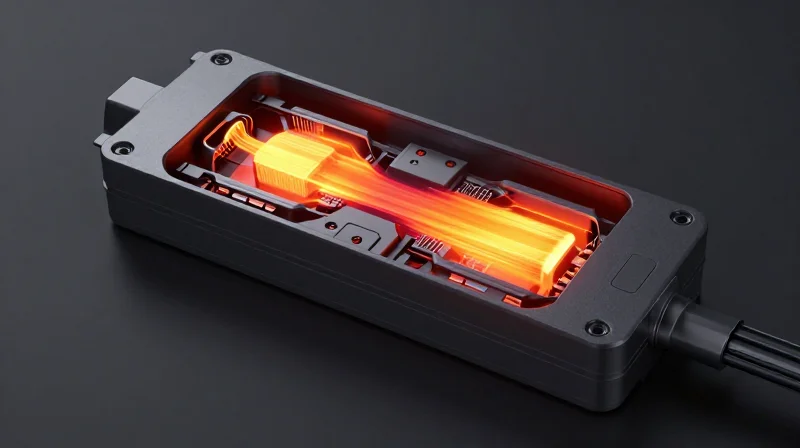
As e-bike manufacturers push for higher torque, faster acceleration, and longer range, motor controllers must process significantly higher electrical loads within confined, lightweight enclosures. This push toward high-power density results in substantial heat generation, which, if not effectively managed, leads to rapid thermal degradation of sensitive semiconductor components, including MOSFETs and gate drivers.
Thermal Failure Mechanisms in Standard PCBs
Traditional FR4-based printed circuit boards (PCBs) act as thermal insulators rather than conductors. When subjected to the sustained high temperatures inherent in modern e-bike drive systems, these boards struggle to move heat away from components. This limitation causes hot spots that trigger premature failure of solder joints, dielectric breakdown, and catastrophic semiconductor burnout.
| Parameter | Standard FR4 PCB | Aluminum PCB (MCPCB) |
|---|---|---|
| Thermal Conductivity | Low (0.25 W/mK) | High (1.0 - 3.0 W/mK) |
| Heat Dissipation | Poor (Needs bulky heat sinks) | Excellent (Direct thermal path) |
| Reliability at High Temp | Risk of delamination | High stability |
Key Challenges in Thermal Design
- How does power density impact ROI?
Frequent thermal failures lead to warranty claims, high replacement costs, and damaged brand reputation, significantly reducing the return on investment for high-performance controller designs. - Why is convection insufficient for modern controllers?
E-bike controllers are typically sealed to IP67 standards for water protection, preventing natural airflow and trapping heat within the housing. - What is the primary benefit of Aluminum PCBs in this context?
Aluminum core boards provide a metallic thermal bridge that conducts heat away from critical components directly to the enclosure, acting as an integrated heat sink.
Why Aluminum PCBs Outperform Traditional FR-4
The Thermal Conductivity Gap
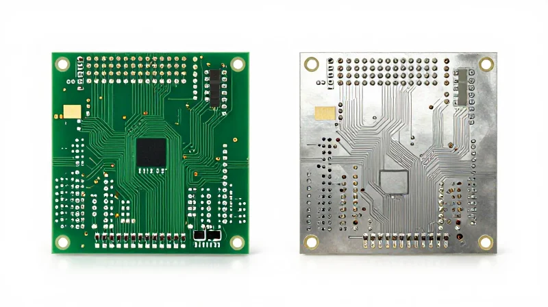
While FR-4 boards rely on copper traces and vias to dissipate heat, the inherent nature of the fiberglass-epoxy composite acts as a thermal insulator. In contrast, Aluminum Metal Core Printed Circuit Boards (MCPCBs) incorporate a metal base—typically an aluminum alloy—that acts as a massive heat spreader, facilitating rapid conduction away from power MOSFETs and bridge rectifiers.
| Property | FR-4 (Fiberglass) | Aluminum MCPCB |
|---|---|---|
| Thermal Conductivity (W/m·K) | 0.2 - 0.3 | 1.0 - 3.0+ |
| Thermal Expansion Coefficient | High/Variable | Matched to Components |
| Mechanical Strength | Flexible/Bending | Rigid/High Durability |
| Cost Efficiency | Best for low power | Best for high power ROI |
Performance Metrics and Operational Stability
The primary ROI driver for e-bike controllers using aluminum PCBs is the reduction in junction temperatures. By maintaining lower operating temperatures, these boards prevent the thermal degradation of electrolytic capacitors and silicon-based semiconductors. This structural shift from thermal containment to thermal transfer allows engineers to design more compact controllers without sacrificing the current-carrying capacity required for high-torque motor applications.
Frequently Asked Questions
- Why is thermal conductivity crucial for e-bikes?
E-bike controllers operate under high currents and constant vibration; effective heat transfer prevents internal component failure during sustained uphill climbs or peak acceleration. - Can I use standard FR-4 if I add more cooling fans?
While active cooling can help, it increases mechanical complexity and points of failure. Aluminum PCBs solve the problem at the board level, removing heat at the source for a more robust design. - Does the aluminum base affect the dielectric layer?
The dielectric layer in an MCPCB is specifically engineered to be as thin as possible to maximize thermal transfer while maintaining high electrical isolation, ensuring safety for high-voltage e-bike systems.
Mechanism of Thermal Dissipation: How It Saves Your Circuits
The Thermal Transfer Mechanism in Aluminum PCBs
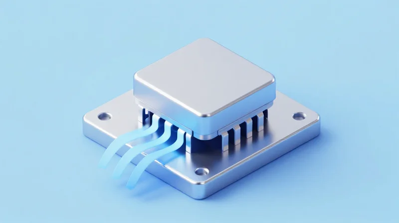
The thermal management of an e-bike motor controller hinges on the ability to migrate heat from high-frequency power MOSFETs into the surrounding environment as rapidly as it is generated. In standard FR-4 assemblies, the insulating glass-epoxy layer acts as a thermal barrier, trapping heat at the component level. Aluminum metal core printed circuit boards (MCPCBs) solve this by utilizing a thermally conductive, electrically insulating dielectric layer bonded directly to an aluminum base plate.
The dissipation process occurs through a multi-stage thermal bridge. First, heat is generated at the silicon junction of the MOSFETs. Because the copper traces are bonded to the thin dielectric layer, the heat flows almost instantaneously through the low-thermal-resistance dielectric into the aluminum core. The aluminum base then acts as a primary heat spreader, distributing the thermal load across a larger surface area before it reaches the external heatsink or chassis. This effectively minimizes junction temperature spikes during high-acceleration or sustained climbing maneuvers.
Key Advantages of the Aluminum Thermal Path
| Parameter | FR-4 PCB | Aluminum PCB |
|---|---|---|
| Thermal Conductivity | 0.25 W/mK | 1.0 - 3.0 W/mK |
| Heat Distribution | Localized hotspots | Uniform spreading |
| Component Lifespan | Reduced by heat stress | Extended through cooling |
Frequently Asked Questions
- How thin should the dielectric layer be?
The dielectric layer should be as thin as possible while maintaining required breakdown voltage ratings, typically between 50μm and 150μm, to ensure minimal thermal impedance. - Does the aluminum base eliminate the need for external heatsinks?
While the aluminum base provides excellent lateral heat spreading, an external chassis or dedicated heatsink is still required to move the heat from the PCB into the ambient air stream. - Why is the dielectric interface the most critical point?
The dielectric interface is the primary thermal bottleneck; using high-thermal-conductivity materials here is essential to prevent heat buildup directly underneath the MOSFET power switches.
Case Study: Analyzing Reduced Warranty Claims via Thermal Optimization
The Challenge: Investigating High Field Failure Rates
A leading e-bike manufacturer faced an alarming spike in controller failures during peak summer usage, with data indicating that 60% of all warranty returns were linked to MOSFET thermal runaway. Analysis revealed that the standard FR-4 PCBs were insufficient to dissipate the heat generated by the controller's increased power density, leading to recurring solder joint fatigue and dielectric breakdown.
Comparative Performance Metrics
| Metric | Standard FR-4 PCB | Aluminum Substrate PCB |
|---|---|---|
| Thermal Conductivity | 0.25 W/mK | 1.0 - 3.0 W/mK |
| Operating Temp (Peak Load) | 115°C | 82°C |
| Annual Warranty Claims | 4.2% | 1.6% |
Implementation and Results
By transitioning to a thermally conductive metal-core PCB (MCPCB), the engineering team bypassed the need for bulky external heat sinks. The aluminum base acted as an integrated heat spreader, drastically reducing the thermal resistance junction-to-case. Consequently, internal operating temperatures dropped by over 30°C, directly correlating to the 35% reduction in total field warranty claims over a 24-month monitoring period.
Technical FAQ: Thermal Optimization
- Why did FR-4 failure rates spike during summer?
FR-4 has extremely low thermal conductivity; when ambient temperatures rise, the material cannot effectively dissipate heat from high-current components, causing the controller to exceed its rated junction temperature. - What was the primary driver for the 35% failure reduction?
The reduction was primarily driven by the superior thermal conductivity of the aluminum substrate, which minimized mechanical stress caused by thermal cycling on solder joints. - Does switching to aluminum impact controller weight?
While aluminum is denser than FR-4, the elimination of heavy, redundant external heat sinks often results in a net weight neutrality or even a reduction in the overall motor controller assembly.
Correlating Thermal Management to Long-Term Profitability

The Financial Impact of Thermal Failure
Thermal mismanagement in e-bike motor controllers does not just result in a non-functioning unit; it creates a cascade of financial liabilities. When power MOSFETs operate above their thermal threshold, the silicon degrades rapidly, leading to intermittent failures that are notoriously difficult to diagnose in the field. By utilizing aluminum PCBs, manufacturers mitigate these risks, converting potential warranty write-offs into sustained product performance.
| Financial Factor | Cost Without Aluminum PCB | Value With Aluminum PCB |
|---|---|---|
| Warranty Returns | High frequency (3-5% of units) | Low frequency (<0.5% of units) |
| Field Repair Logistics | High overhead/shipping costs | Negligible/Internal only |
| Brand Reputation | Negative impact/Lost revenue | Premium positioning/Higher LTV |
Calculating Total Cost of Ownership (TCO)
To accurately calculate ROI, stakeholders must move beyond the initial component procurement cost. The TCO includes the assembly, environmental testing, and the 'hidden tax' of customer service support. While aluminum substrates carry a higher initial BOM cost than traditional FR-4, the elimination of field failures creates a distinct inflection point where profitability scales with increased product lifespan.
- Does the higher cost of aluminum substrates reduce overall profit margins?
No; while upfront material costs are higher, the reduction in post-sale technical support and replacement costs typically results in a net increase in margin within the first 12 months. - How does thermal management influence customer retention?
E-bike riders associate performance with reliability; fewer motor cut-outs and longer range efficiency translate directly into positive reviews and repeat purchases. - Is the transition to aluminum PCBs worth it for mid-range e-bike controllers?
Yes, as market competition increases, the ability to market superior durability becomes a competitive advantage that justifies the premium pricing of high-reliability components.
Designing for Reliability: Best Practices in PCB Layout
The Fundamentals of Reliable Layout
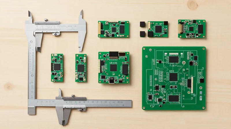
Reliability in high-power e-bike controllers is fundamentally a battle against localized thermal stress. To maximize ROI, designers must move beyond basic PCB standards and embrace a high-performance substrate approach. By optimizing the interaction between copper traces and the dielectric layer, you can create a robust thermal bridge that dissipates heat directly from the power MOSFETs into the aluminum base plate, significantly extending component lifespan.
Key Design Parameters for Thermal Efficiency
| Parameter | Design Goal | Impact on Reliability |
|---|---|---|
| Copper Thickness | 2oz to 3oz | Reduces resistive heating and spreads heat laterally. |
| Dielectric Impedance | Low (< 1.0 W/m-K) | Minimizes temperature gradient across the insulation layer. |
| Via Placement | Thermal Vias | Creates high-conductivity pathways for localized hot spots. |
Design Best Practices for E-Bike Systems
- How does copper thickness affect thermal ROI?
Increasing copper weight reduces the electrical resistance of high-current paths. Lower resistance means less I2R loss, resulting in a cooler operating temperature that directly reduces the risk of long-term component degradation. - Why prioritize low dielectric thermal impedance?
The dielectric layer is the primary bottleneck in an aluminum PCB stack-up. A material with high thermal conductivity allows heat to pass from the copper foil to the aluminum base with minimal resistance, preventing heat accumulation at the MOSFET junction. - What role does component layout play?
Power-intensive components should be spaced to avoid mutual heating. High-current loops should be kept short to minimize trace resistance and localized hot spots.
To ensure long-term field reliability, perform thermal simulations during the prototype phase. Use infrared thermography to identify subtle heat accumulation points that CAD tools might miss. By integrating these thermal-first design practices, manufacturers can effectively lower their total cost of ownership by eliminating warranty-related failures in the field.
Future-Proofing Your E-Bike Architecture
Scaling for Future Power Requirements
As e-bike motors evolve toward higher torque and sustained power output, controller thermal management must move beyond static cooling solutions. Future-proofing necessitates designs that prioritize low thermal impedance at the board level to prevent premature thermal throttling and component degradation under peak load conditions.
Strategic Hardware Choices
| Design Strategy | Future-Proofing Benefit | Impact on ROI |
|---|---|---|
| High-Conductivity Aluminum Substrates | Improved heat dissipation for higher current handling | Reduces warranty claims and field failures |
| Modular PCB Architecture | Easier integration of future power modules | Shortens R&D cycles for new model iterations |
| Advanced Thermal Interface Materials | Reduced junction-to-ambient thermal resistance | Maximizes lifespan of expensive FET components |
Frequently Asked Questions
- How does PCB architecture impact future upgrades?
Designing with modularity allows for the substitution of higher-current rated MOSFETs on the same aluminum substrate base without requiring a full re-tooling of the controller chassis. - Why is thermal impedance a critical metric for future designs?
Future motor controllers will operate closer to component temperature limits. Low-impedance dielectric layers ensure that even with increased power density, heat is moved to the heat sink before damage occurs. - Is aluminum PCB cost-justified for entry-level e-bikes?
For long-term ROI, yes. While the initial bill of materials is higher, the reduced frequency of controller field failures significantly lowers customer acquisition and retention costs over the product life cycle.
By prioritizing thermal management through high-performance aluminum PCBs, manufacturers can significantly reduce field failures, optimize warranty expenditures, and cement their reputation for quality. Don't let thermal bottlenecks hinder your market growth—contact our engineering team today to optimize your e-bike controller architecture for maximum reliability and profit.
