
In the hyper-competitive world of IoT and industrial sensing, achieving consistent thermal precision across millions of units is the ultimate engineering hurdle. This article breaks down the DFM (Design for Manufacturing) complexities that transform a prototype from a high-accuracy sensor into a scalable, high-volume product.
The Fundamentals of Precision Thermal Sensing Architecture
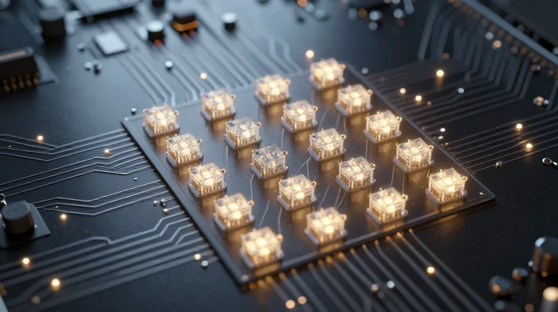
Architectural Pillars for Precision Thermal Sensing
Achieving high-accuracy thermal measurement in high-volume PCBA requires a shift from simple component selection to rigorous system-level architectural design. The foundation rests on managing the analog front-end (AFE) to preserve signal integrity before digitization. Minimizing parasitic resistances and mitigating thermal gradients across the board are essential to ensure the conversion process remains faithful to the sensor's raw output.
Signal-to-Noise Ratio (SNR) Management
Noise is the primary enemy of precision. In high-density PCBAs, digital switching noise often couples into sensitive analog paths. Designers must implement localized star-grounding and differential signaling to reject common-mode noise. Furthermore, the sampling frequency must be carefully chosen to avoid alias frequencies that can pollute the thermal data stream.
| Design Factor | Impact on Precision | Mitigation Strategy |
|---|---|---|
| Trace Impedance | Voltage Drops/Error | Wide, symmetric routing |
| EMI/RFI Coupling | Signal Jitter | Faraday cage shielding |
| Thermal Gradients | Drift | Balanced thermal planes |
Low-Drift Design Principles
Thermal drift manifests through component aging and PCB mechanical stress. To combat this, designs must incorporate low-drift voltage references and ratiometric measurement architectures. By measuring the sensor output relative to the same excitation source, the system effectively cancels out common errors introduced by source voltage fluctuations.
- Why is ratiometric measurement critical?
It allows the system to remain insensitive to excitation voltage drifts, as both the sensor and the reference utilize the same supply. - How does board layout affect drift?
Mechanical stress from PCB warping or temperature-induced expansion can alter resistance values in bridge circuits, necessitating precise component placement. - Is software calibration sufficient?
Software can correct predictable offsets, but it cannot fix poor SNR or non-linear noise, highlighting the need for hardware-level precision.
Strategic Component Selection for Long-term Stability
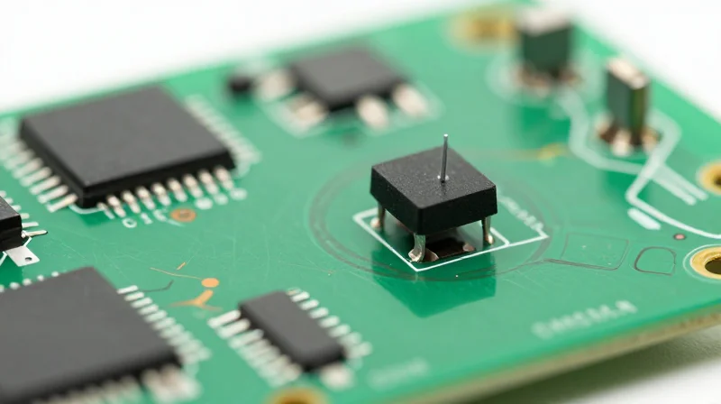
Selecting High-Precision Components for Thermal Reliability
Achieving long-term stability in digital thermometers requires a meticulous approach to component selection that prioritizes aging characteristics, thermal drift, and robust tolerance margins. Engineers must move beyond initial datasheet specs, focusing instead on how these components behave after thousands of hours in operation and varying environmental conditions.
Thermistors and IC Aging Characteristics
NTC thermistors and integrated sensing ICs are prone to drift caused by humidity ingress, thermal cycling, and physical stress. For high-volume PCBA, selecting components with low-aging coefficients is mandatory to maintain clinical accuracy over a multi-year shelf life. Designers should specify hermetically sealed components or high-stability epoxy coatings to minimize environmental degradation.
| Component Type | Key Stability Metric | Recommended Margin |
|---|---|---|
| NTC Thermistor | Resistance Drift / Year | <0.1% R25 shift |
| Precision ADC/IC | Gain Error Over Time | <5ppm/°C |
| Reference Voltage | Long-term Stability | <50ppm/1kHr |
Design Guidelines for Tolerance and Drift
- How does moisture impact sensor longevity?
Moisture ingress can alter the resistance characteristics of thermistor beads; using components with high-grade glass encapsulation or moisture-resistant polymers is critical. - Why is the initial tolerance margin insufficient?
Initial tolerance only reflects manufacturing variance. Long-term stability requires analyzing the 'total error budget' which includes drift, soldering stress, and hysteresis. - What role does thermal cycling play?
Rapid transitions between ambient and body temperatures can introduce mechanical stress; selecting components with matched thermal expansion coefficients minimizes internal fatigue.
Advanced PCB Layout Strategies for Thermal Isolation

Minimizing Self-Heating and Thermal Coupling
In precision thermometry, the PCB is not just a carrier but a thermal conductor that can introduce bias. To ensure the sensor measures the ambient environment rather than internal heat dissipation, designers must isolate the sensing element from high-power components like microcontrollers, voltage regulators, and power MOSFETs.
Layout Optimization Strategies
- Thermal Slotting and Air Gaps
Implement PCB milling slots around the sensor area to physically restrict the conductive path for heat traveling through the FR-4 substrate. - Copper Pour Management
Remove copper pours near the thermistor to reduce heat sink effects. Use thermal relief pads on traces connected to the sensor to limit conduction. - Component Placement
Maintain a 'thermal keep-out zone' where no high-dissipation components are placed on the same side or directly beneath the sensor on the opposite layer.
Thermal Management Comparison
| Strategy | Effectiveness | Primary Application |
|---|---|---|
| Thermal Slots | High | Preventing substrate conduction |
| Copper Pour Removal | Medium | Local heat sink mitigation |
| Trace Thinning | Low | Reducing lead self-heating |
Frequently Asked Questions
- How does PCB thickness influence sensor accuracy?
Thicker boards have a higher thermal mass and conductivity, which can lead to longer time constants for temperature stabilization and increased lateral heat spreading. - Should I use thermal vias near the sensor?
No. Thermal vias are specifically designed to move heat between layers; their presence near a precision sensor will allow board-level heat to reach the component, introducing significant measurement errors.
Mitigating Environmental Noise and EMI Interference
Differential Signaling and Signal Integrity
To achieve high-precision temperature sensing, the signal path must be immune to common-mode noise generated by industrial machinery and power electronics. Implementing fully differential signaling for the thermistor excitation and sensing path allows for the cancellation of induced noise. By ensuring trace length matching and tight coupling, engineers can significantly reduce the effective loop area, which minimizes radiated emissions and susceptibility to external magnetic fields.
Shielding and Board-Level Grounding Strategies
Physical shielding is the first line of defense against high-frequency EMI. For volume production, the enclosure should integrate conductive gaskets or metallized coatings to create a Faraday cage around sensitive analog front-end (AFE) components. Internally, a multi-layer stack-up is essential, utilizing dedicated ground planes beneath sensitive signals to provide low-impedance return paths and mitigate crosstalk.
| Noise Source | Mitigation Strategy | Implementation Priority |
|---|---|---|
| 50/60Hz Power Line | Differential filtering & notch filters | High |
| High-Frequency RF | Ferrite beads & metal shielding | Medium |
| Switching Power Supplies | Physical isolation & ground partitioning | High |
Common EMI and Noise Mitigation FAQs
- How do I choose the right ferrite bead for my AFE?
Select a ferrite bead that provides high impedance at the expected interference frequency without introducing excessive DC resistance that could cause voltage drops in the sensor bias. - Is a split ground plane necessary?
While often recommended, split planes can create unexpected return path issues; a single high-quality ground plane with careful component placement is generally superior to separate analog and digital planes for mixed-signal thermometers. - Why does my sensor reading drift in industrial sites?
Drift is often caused by EMI rectifying into DC offsets through non-linear junctions in the AFE; robust input filtering and ensuring clean power rails are the primary solutions.
Optimizing Assembly Protocols for High-Volume PCBA
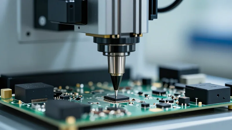
Refining SMT Processes for Precision Components
High-volume assembly of digital thermometers necessitates extreme repeatability in SMT placement, particularly for thermistor leads and micro-controllers. Automated Optical Inspection (AOI) must be integrated post-placement to detect minute misalignment before reflow, preventing common soldering defects such as tombstones or solder bridging, which are fatal to temperature sensing accuracy.
Stencil Design and Solder Paste Control
Optimizing solder volume is critical for maintaining consistent thermal contact and electrical impedance. Stencil thickness should be tailored to the smallest component pitch on the board; typically, a 0.10mm to 0.12mm laser-cut stainless steel stencil is recommended to ensure adequate paste release for fine-pitch sensor pads without excessive overflow.
| Component Type | Stencil Thickness | Aperture Design |
|---|---|---|
| 0201/0402 Passives | 0.10 mm | 1:1 Square |
| Precision ICs | 0.12 mm | Homeplate/Rounded |
| Thermistor Pads | 0.10 mm | 1:1 Ratio |
Optimizing Thermal Reflow Profiles
The reflow profile must be customized to prevent damage to sensitive sensors while ensuring complete solder wetting. A 'soak' profile is often superior to a 'ramp-to-spike' method for thermometers, as it minimizes thermal shock to the thermistor crystal and ensures uniform heat distribution across the PCB, preventing warping that could lead to intermittent connections.
- How do I prevent thermal stress during reflow?
Implement a controlled soak zone (150-180°C) to allow the board and components to reach equilibrium before entering the liquidus phase. - Why does solder bridge occur at high volume?
Usually due to excessive stencil thickness or high-pressure placement heads. Verify solder paste viscosity and decrease squeegee pressure. - How can I verify thermal bonding quality?
Utilize cross-sectional X-ray analysis on pilot batches to inspect hidden solder joints under BGA or CSP sensors for voiding percentage.
Automated Calibration and Validation Procedures

Integrated Calibration Architectures
To achieve high-throughput production, calibration must be integrated directly into the assembly line. Automated Test Equipment (ATE) interfaces with the PCBA via dedicated test points, allowing for simultaneous multi-point sensor stimulation. By employing high-precision thermal chambers that transition rapidly between setpoints, manufacturers can characterize the thermistor response curve across the full operating range, applying correction coefficients directly to the device firmware.
Calibration Methodology vs. Validation Standards
| Procedure | Objective | Standard |
|---|---|---|
| In-Circuit Calibration | Offset/Gain trimming | Internal ATE Reference |
| Thermal Characterization | Sensor curve linearization | NIST Traceable Bath |
| Final Validation | Pass/Fail criteria verification | IEC 60751 / ASTM E1137 |
Ensuring NIST Traceability
Traceability is maintained through periodic certification of the ATE measurement system against master reference standards. Every calibrated unit should store its specific calibration date and offset values in non-volatile memory (EEPROM/Flash), ensuring that long-term field drift can be tracked or corrected through future software updates.
Frequently Asked Questions
- How is thermal latency mitigated in ATE?
ATE systems use specialized copper heat-spreader jigs or thermal transfer fluids to minimize the latency between the chamber temperature and the actual sensor die temperature, ensuring accurate stabilization before data capture. - What is the recommended sample size for validation?
A Cpk (Process Capability Index) analysis should be used to determine sample sizes, typically targeting 100% calibration for initial batches and moving to statistically significant sampling as the process matures. - Can calibration coefficients be applied post-assembly?
Yes, utilizing a 'Golden Unit' comparison in the final assembly stage allows for firmware-level adjustments to compensate for minor component variations introduced during the SMT reflow process.
Quality Control Metrics and Statistical Process Control (SPC)
Establishing Cpk and Ppk Benchmarks
To ensure long-term manufacturing stability, process capability must be quantitatively defined. Cpk measures the potential of a process to stay within specification limits, while Ppk assesses the actual performance over time. For high-volume medical-grade digital thermometers, a Cpk of 1.67 or higher is the industry standard, indicating a robust process that minimizes the probability of out-of-specification thermal readings.
| Metric | Focus | Target Value | Significance |
|---|---|---|---|
| Cpk | Short-term Stability | >1.67 | Confirms process center and spread |
| Ppk | Long-term Performance | >1.33 | Accounts for total process variation |
Early Detection of Thermal Drift
SPC charts, specifically X-bar and R charts, are deployed during the automated calibration phase to track the mean value of thermal sensor outputs. By plotting real-time data against control limits, manufacturers can identify 'assignable cause' variations—such as solder degradation or environmental shifts in the cleanroom—before they result in scrap.
- How does SPC mitigate risk in high-volume PCBA?
By providing a real-time visualization of process trends, SPC allows for the immediate adjustment of machinery before drift impacts the final sensor accuracy. - What triggers an out-of-control alarm in thermometer production?
An alarm is triggered if data points violate Nelson rules, such as seven consecutive points on one side of the mean, indicating a systemic shift in sensor bias. - Why differentiate between Cpk and Ppk in this context?
Cpk validates that the assembly equipment setup is optimal, while Ppk incorporates the fluctuations of real-world environment factors and component aging over thousands of units.
Ultimately, the transition from reactive quality assurance to proactive statistical management ensures that every digital thermometer produced maintains the tight precision required for clinical diagnostics.
Design for Reliability: Testing for Harsh Environments
Accelerated Life Testing (ALT) Frameworks
To guarantee reliability in high-volume PCBA manufacturing, design teams must implement Accelerated Life Testing (ALT) to simulate years of field usage in a fraction of the time. By subjecting components to elevated temperatures, thermal cycling, and humidity, engineers can identify latent defects that would otherwise cause premature failure in medical or consumer-grade environments.
| Stress Type | Test Objective | Common Failure Mode |
|---|---|---|
| Thermal Shock | Assess solder joint fatigue | Intermittent contact or cracking |
| High-Temp/Humidity (85/85) | Test enclosure seal and IC integrity | Electrochemical migration or corrosion |
| Vibration/Mechanical Shock | Verify PCB mounting stability | Component displacement or fracture |
Environmental Stress Screening (ESS) Protocols
Environmental Stress Screening serves as a post-manufacturing filter to catch infant mortality cases. Implementing a robust ESS strategy—typically comprising rapid temperature cycling and power-on vibration—ensures that every device departing the line meets established durability benchmarks.
- How does moisture ingress affect sensor accuracy?
Moisture can cause drift in thermistor readings or create conductive paths on the PCBA. Reliable DFM design utilizes conformal coatings and IP-rated enclosures to isolate the sensor and sensitive logic circuitry. - Why is thermal cycling critical for handheld thermometers?
Handheld units face rapid temperature shifts when moving from ambient storage to patient skin contact; thermal cycling tests reveal if expansion coefficients of different materials cause solder joint degradation over time. - What is the recommended duration for an initial reliability batch test?
While it depends on the target MTBF, a standard validation cycle includes at least 1,000 hours of continuous operation at 90% of the maximum thermal limit to ensure high-volume consistency.
Successfully manufacturing high-accuracy digital thermal modules requires a seamless marriage between rigid design standards and scalable production automation. By implementing these DFM protocols, you ensure that precision is not just a laboratory achievement, but a standard feature of every unit shipped. Contact our engineering team today to optimize your thermal sensing product for your next large-scale production run.
