
In the high-stakes world of medical imaging, even a microscopic trace of magnetic impurity can compromise diagnostic clarity. As MRI field strengths increase, the demand for non-magnetic PCB materials has shifted from a best practice to an absolute necessity. This guide provides the authoritative framework engineers need to select substrates and conductors that guarantee performance without disrupting the magnetic homogeneity of your scanners.
Understanding the Physics of Magnetic Interference in MRI

The Physics of Magnetic Interference in MRI
In a high-field MRI environment, the static magnetic field (B0) is extremely sensitive to any variations in the local magnetic environment. When a PCB is placed within or near the scanner's bore, any material with non-zero magnetic susceptibility interacts with the B0 field. If a material is ferromagnetic or paramagnetic, it creates local field distortions—known as susceptibility artifacts—which manifest as geometric distortions or signal voids in the resulting clinical image.
Magnetic Susceptibility and Field Distortions
Magnetic susceptibility (χ) is a dimensionless proportionality constant that indicates the degree of magnetization of a material in response to an applied magnetic field. Materials are broadly categorized based on this constant:
| Classification | Susceptibility (χ) | Impact on MRI |
|---|---|---|
| Diamagnetic | Negative (Weak) | Negligible impact; ideal for MRI hardware. |
| Paramagnetic | Positive (Weak) | Potential for localized field shift; requires testing. |
| Ferromagnetic | Positive (Strong) | Significant distortion; causes severe artifacts and safety hazards. |
Key Considerations for Material Selection
- Why is pure copper cladding preferred?
Copper is diamagnetic, meaning it exhibits minimal interaction with the magnetic field, preventing the induction of large local magnetic gradients. - What is the danger of using nickel plating?
Nickel is ferromagnetic and is frequently used in PCB manufacturing as an under-layer for gold plating. Even small amounts can create significant image artifacts and force the PCB to experience physical attractive forces within the scanner. - How does substrate weave affect performance?
While the dielectric substrate itself is usually non-magnetic, structural inconsistencies or embedded metallic reinforcements in the weave can create subtle inhomogeneity, necessitating high-purity resin systems.
Substrate Selection: Beyond Standard FR-4
The Limitations of FR-4 in High-Field Environments
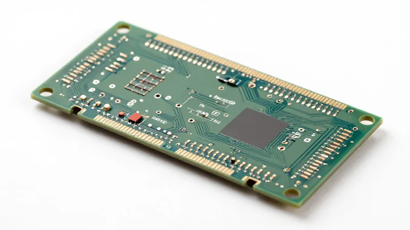
Standard FR-4, while cost-effective for consumer electronics, is fundamentally unsuitable for high-field MRI environments. The primary concern is the presence of glass-fiber reinforcement and halogenated flame retardants that can exhibit non-negligible magnetic susceptibility. In an MRI gradient field, even trace amounts of paramagnetic impurities within the resin or fiberglass weave can cause localized magnetic field distortions, resulting in image artifacts and signal instability. Furthermore, FR-4 lacks the dielectric consistency required for the high-frequency RF pulses used in modern imaging sequences.
Material Comparison: Evaluating High-Performance Alternatives
| Material Class | Magnetic Susceptibility | Dielectric Stability | Suitability |
|---|---|---|---|
| Standard FR-4 | High/Variable | Moderate | Unsuitable |
| PTFE-Based (Ceramic Filled) | Very Low | Excellent | Ideal |
| Hydrocarbon/Ceramic | Low | Excellent | High |
| Polyimide | Low | Good | Specialized |
Key Considerations for Substrate Selection
- Magnetic Susceptibility (Permeability)
Materials must be chosen with a magnetic permeability as close to 1.0 (vacuum) as possible. Manufacturers should provide certification that substrates are free from paramagnetic or ferromagnetic impurities, particularly in the bonding agents. - Dielectric Constant (Dk) Stability
For RF coil design, the Dk must remain stable across varying temperatures and humidity levels. Fluctuations in Dk directly shift the resonant frequency of the coil, degrading the signal-to-noise ratio. - Thermal Management
High-field imaging generates significant heat during rapid gradient switching. Substrates with high thermal conductivity help dissipate heat, preventing local thermal expansion that could mechanically shift components and disrupt field uniformity.
Prototyping Strategy
When qualifying a new substrate, it is recommended to conduct benchtop testing using a sensitivity map. By exposing candidate materials to a static magnetic field of similar strength to the target MRI (e.g., 3T or 7T), engineers can perform X-ray inspection to detect any latent magnetic inclusions within the laminate structure. Prioritize PTFE-based substrates with ceramic fillers, as these offer the most predictable electrical performance and the highest probability of being inherently non-magnetic.
Evaluating Conductive Materials and Plating Finishes
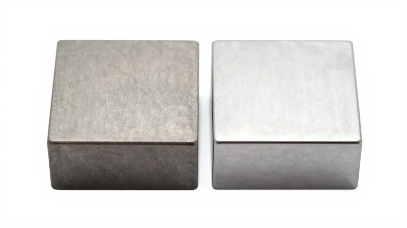
In MRI-compatible electronics, the selection of conductors is as critical as the choice of dielectric substrate. Even trace amounts of ferromagnetic contaminants within plating baths or base copper layers can induce localized magnetic flux distortions. These distortions, often invisible in standard industrial applications, manifest as catastrophic artifacts in clinical diagnostic imaging. Engineers must prioritize high-purity copper and explicitly non-magnetic finish specifications to ensure hardware remains invisible to the 1.5T or 3T main magnetic field.
Optimizing Copper Purity and Trace Metallurgy
High-field MRI systems demand extreme material purity. While electrolytic tough-pitch copper is common, it may contain trace elements that interfere with RF coils or superconducting magnets if not strictly controlled. For high-sensitivity applications, specifying certified high-purity copper layers reduces the risk of inclusions. Furthermore, all structural components such as edge plating or thermal vias must avoid nickel-based barriers, as nickel's inherent ferromagnetism creates significant signal voids.
Comparison of Common PCB Plating Finishes
| Finish Type | Magnetic Status | Suitability for MRI |
|---|---|---|
| ENIG (Immersion Gold) | Contains Nickel Layer | Generally Unsuitable |
| ENEPIG | Contains Nickel/Palladium | Avoid for High-Field |
| Immersion Silver | Non-Magnetic | Excellent |
| Immersion Tin | Non-Magnetic | Good |
| OSP (Organic Solderability) | Non-Magnetic | Excellent |
Selecting Non-Ferrous Finishes
The industry-standard Electroless Nickel Immersion Gold (ENIG) process is largely incompatible with high-field MRI scanners due to the mandatory nickel barrier layer. Nickel's high magnetic susceptibility makes it an primary source of B0 field inhomogeneity. Designers should instead utilize finishes that leverage non-magnetic transition metals or organic compounds. Immersion silver and OSP provide superior RF performance while maintaining a strictly non-ferromagnetic interface.
Frequently Asked Questions on Conductive Materials
- Can I use standard ENIG for MRI coils?
No, the nickel layer in ENIG is ferromagnetic and will cause signal degradation and magnetic field distortions, leading to image artifacts. - Why is Immersion Silver preferred over ENIG?
Immersion silver is entirely non-magnetic and provides excellent high-frequency conductivity, ensuring the board does not interact with the MRI's powerful magnetic fields. - Are there any hidden risks with PCB vias?
Yes, ensure that any conductive adhesive or fill material used in vias does not contain metallic iron or nickel particles, as these can accumulate magnetic mass.
The Role of Magnetic Permeability in Material Certification
The Role of Magnetic Permeability in Material Certification
For MRI applications, material certification hinges on the verification of magnetic permeability (μ) to ensure the PCB remains virtually invisible to the strong static magnetic field ($B_0$). Even trace amounts of ferromagnetic impurities within resin systems or reinforcement fibers can introduce local magnetic field gradients, leading to severe image distortion or signal voids. Rigorous certification requires manufacturers to quantify the magnetic susceptibility of the bulk material, ensuring it stays within the permissible limits defined by the specific imaging application.
Interpreting Permeability Data Sheets
Standard PCB material data sheets rarely list magnetic permeability by default, as most general-purpose applications consider it negligible. For MRI-grade materials, certification data must be requested explicitly. Engineers should look for values of relative magnetic permeability ($\mu_r$) approaching 1.0000. Materials with $\mu_r > 1.001$ should be scrutinized, as the cumulative effect of a complex PCB stack-up can rapidly exceed the tolerance thresholds of high-tesla systems (3T to 7T+).
| Material Property | Target Value | Significance for MRI |
|---|---|---|
| Relative Permeability (μr) | 1.0000 to 1.0005 | Maintains local B0 field homogeneity. |
| Magnetic Susceptibility (χ) | Diamagnetic/Paramagnetic < 10^-6 | Prevents field distortion and artifacting. |
| Ferrous Impurity Level | Below 50 ppm | Eliminates microscopic 'hot spots' in the imaging volume. |
Frequently Asked Questions on Material Certification
- Why is standard FR-4 often insufficient for MRI coils?
Standard FR-4 contains glass fibers and epoxy resins that may have trace contamination from iron or nickel used in the manufacturing process, resulting in magnetic susceptibility values that cause artifacts. - How can I verify if a batch of material is MRI-safe?
Request a certificate of analysis (COA) specifying magnetic susceptibility measurements or perform sample testing using a SQUID magnetometer if the application involves ultra-high fields. - Does the plating finish affect magnetic certification?
Yes. While the substrate is primary, plating finishes like electroless nickel/immersion gold (ENIG) must be avoided due to the ferromagnetic nature of the nickel layer, opting instead for immersion silver or gold over copper.
Managing Trace Elements and Impurities in Manufacturing

The Impact of Trace Metallic Contaminants
In the construction of high-field MRI scanners, even trace amounts of ferromagnetic contaminants in dielectric substrates or copper foils can result in catastrophic image artifacts. Materials that appear non-magnetic at standard specifications often contain microscopic trace elements—such as iron, nickel, or cobalt—introduced during the raw material manufacturing process. When subjected to the intense magnetic flux of a 3T or 7T system, these impurities can create localized magnetic field gradients that distort RF pulses and induce eddy currents, ultimately degrading signal-to-noise ratios.
Risk Assessment for Common Impurities
| Impurity Type | Common Source | Impact on MRI Imaging |
|---|---|---|
| Iron (Fe) | Roller contact in foil production | Significant field distortion and gradient noise |
| Nickel (Ni) | Barrier plating in connectors | High susceptibility; causes localized RF blocking |
| Cobalt (Co) | Catalytic residual in resin | Background noise increase; reduces image resolution |
Maintaining Supply Chain Integrity and Validation
Mitigating these risks requires more than a standard certificate of compliance; it demands a robust validation strategy that encompasses the entire lifecycle of the PCB material. Manufacturers must enforce strict clean-room protocols for material handling and perform batch-specific testing to verify magnetic susceptibility.
- How is material purity verified for MRI applications?
Verification involves using mass spectrometry to detect trace ppm-level metallic contaminants and SQUID magnetometry to measure the actual magnetic response of a sample batch. - Why is supplier oversight essential?
Because standard industrial-grade materials allow for trace impurities that are irrelevant in consumer electronics but problematic in MRI, direct collaboration with material suppliers is required to ensure 'MRI-grade' purity standards are maintained. - What should be included in a material certificate?
A high-assurance certificate must explicitly state the maximum allowed ppm for nickel and iron, alongside a certified test report confirming the permeability remains below the 1.0001 threshold.
Design Best Practices for High-Field Environments
Minimizing Parasitic Induction in High-Field Geometries
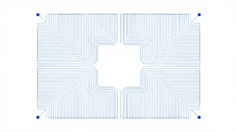
In MRI scanners reaching 3T or 7T, magnetic field gradients can induce significant eddy currents in conductive traces. To mitigate this, PCB designers must prioritize loop area reduction and utilize balanced differential signal routing. Minimizing the physical loop area not only reduces susceptibility to induced electromotive force but also minimizes the Lorentz force exerted on the conductors, preventing mechanical vibration that could otherwise degrade signal-to-noise ratios.
Structural Rigidity and Material Selection
Extreme magnetic environments exert significant mechanical stress on board substrates. Standard FR-4 often lacks the necessary thermal and mechanical stability, risking delamination or trace fatigue under cyclic magnetic pulses. Utilizing high-Tg (glass transition temperature) laminates with low coefficient of thermal expansion (CTE) is essential for maintaining structural integrity.
| Feature | Design Strategy | Reasoning |
|---|---|---|
| Trace Routing | Balanced Differential Pairs | Cancels magnetic field influence and reduces EMI |
| Copper Weight | Thinner foils (0.5oz - 1oz) | Reduces mass susceptible to Lorentz force interaction |
| Vias | Staggered or back-drilled | Limits eddy current paths and prevents field concentration |
Common Implementation Questions
- Does the orientation of the board relative to the B0 field matter?
Yes, orienting the PCB to minimize the surface area perpendicular to the main B0 field lines drastically reduces induced eddy currents. - Can standard surface mount components be used?
Only if they are verified non-magnetic; many SMT packages contain nickel lead frames or steel internals that create significant field artifacts. - Why is board stiffening required?
To prevent mechanical resonance of the substrate caused by rapidly switching gradient fields, which can lead to microphonic noise in sensitive analog circuitry.
Vendor Certification and Quality Assurance Protocols
In the high-field MRI environment, the selection of raw materials is only as reliable as the manufacturer's ability to maintain process integrity. Even high-grade non-magnetic laminates can fail due to contamination during fabrication or inconsistent batch quality. Vendors must demonstrate not only material specifications but also a robust, verifiable chain of custody that spans from resin synthesis to final copper etching.
Essential Vendor Vetting Checklist
- Magnetic Traceability Audit
Request a full material traceability report that identifies the origin of raw fiberglass, epoxy resins, and copper foils, ensuring these sub-suppliers also adhere to non-magnetic standards. - Certificate of Compliance (CoC) Requirements
Every shipment must be accompanied by a CoC that specifically references susceptibility limits, rather than generic ISO standards. - Process Cleanliness Standards
Verify that the PCB fabrication facility utilizes dedicated lines for non-magnetic production to eliminate the risk of ferrous cross-contamination from high-speed drilling or routing equipment.
Quality Assurance: Testing Protocols
| Testing Metric | Frequency | Objective |
|---|---|---|
| Magnetic Susceptibility | Batch-level | Confirm permeability remains below 1.00002 threshold. |
| X-Ray Fluorescence (XRF) | Periodic sampling | Detect trace heavy metals in plating or solder masks. |
| Eddy Current Inspection | 100% inspection | Identify hidden ferrous metallic inclusions. |
FAQ: Managing Supplier Quality
- Should I rely solely on the supplier’s datasheet?
No; datasheets reflect ideal performance. You must require independent third-party lab verification for magnetic permeability on your specific material batches. - What is the biggest risk during the assembly phase?
The introduction of hidden magnetic contaminants, such as iron-based debris from cutting tools or nickel-based barrier layers in surface finish processes, is the most frequent cause of field failure.
Selecting the correct materials is the foundation of high-performance MRI hardware, directly impacting both diagnostic reliability and patient safety. By rigorously vetting your supply chain and prioritizing non-magnetic material certification, you can effectively mitigate risks and accelerate time-to-market. Ready to optimize your hardware for the next generation of medical imaging? Contact our engineering team today for a consultation on your non-magnetic PCB specifications.
