
In the fast-evolving sector of personal electric mobility, selecting the right motor controller is not just a procurement decision—it is a critical engineering commitment. For electric wheelchair applications, the controller sits at the heart of user safety and device longevity. This guide cuts through the technical jargon to help you navigate the essential balancing act between peak current demands, thermal overhead, and rigorous medical safety compliance.
Evaluating Power Density and Peak Current Ratings
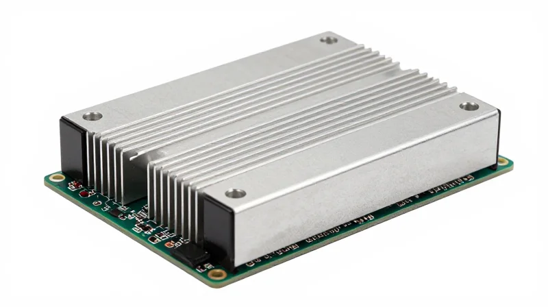
To effectively evaluate power density, engineers must reconcile the physical footprint of the motor controller with the rigorous demands of high-torque starts and variable terrain traversal. High-current motor controllers for electric wheelchairs are often limited by thermal dissipation capabilities; therefore, the selection process centers on the intersection of peak current capacity and the controller's ability to handle thermal excursions without triggering a current-foldback state.
Peak Current vs. Continuous Current Requirements
The distinction between continuous and peak current ratings is often the difference between a stalled chair and one that surmounts a steep incline. Peak current must account for the locked-rotor torque required during initialization or sudden changes in direction on inclined surfaces. Ideally, the controller’s peak current rating should exceed the motor's peak stall current by a safety margin of at least 20% to account for peak efficiency drops during battery depletion.
| Operating Scenario | Current Load Type | Duration Expectation |
|---|---|---|
| Steady Flat Ground | Continuous | 100% duty cycle |
| Incline Start-up | Peak | 5 to 15 seconds |
| Obstacle Clearance | Peak | Under 3 seconds |
Optimizing Footprint without Sacrificing Thermal Performance
Increasing power density within a compact chassis requires careful consideration of the MOSFET switching frequency and PCB thermal conductivity. High-density designs benefit from modern Wide Bandgap (WBG) materials like Silicon Carbide (SiC) or Gallium Nitride (GaN), which offer lower switching losses and smaller cooling requirements. When choosing a controller, prioritize units with integrated thermal management interfaces that allow for chassis-based heat sinking to maximize continuous power delivery.
Engineering FAQ: Current Rating Considerations
- How do I calculate the minimum required peak current?
Multiply the motor's stall current by 1.25 to provide a buffer for battery voltage drops, ensuring the controller does not engage over-current protection during high-torque events. - Does high switching frequency increase current capacity?
No, a higher switching frequency typically increases switching losses, which can reduce the effective continuous current rating unless superior MOSFETs and thermal dissipation paths are utilized. - Why does my controller enter current-foldback?
The internal controller temperature has likely exceeded its threshold due to sustained high-current draws; this is a protective feature that limits current to prevent permanent MOSFET failure.
Advanced Thermal Management Strategies
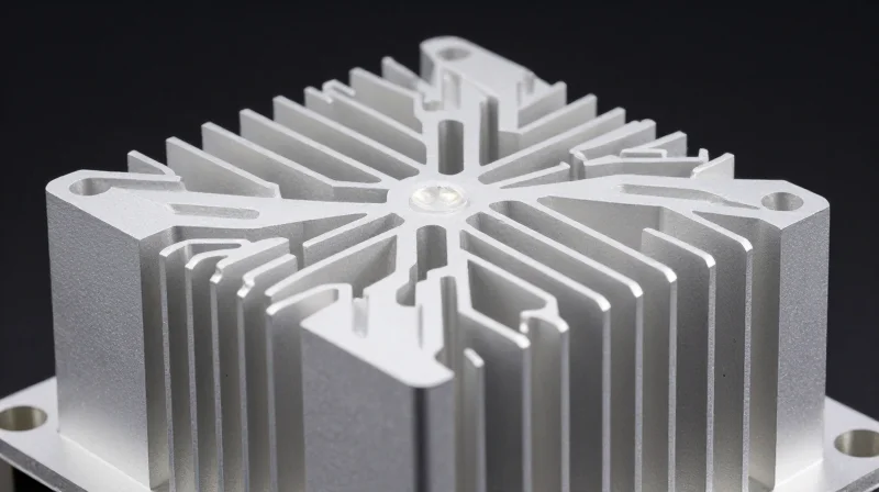
As electric wheelchairs operate in diverse environments, from steep inclines to high-friction carpet, the motor controller must shed significant heat generated by conduction and switching losses. Advanced thermal design moves beyond simple passive cooling to incorporate high-performance PCB materials, optimized copper traces, and integrated thermal interfaces.
Optimizing PCB Architecture for Thermal Conductivity
Standard FR4 substrates often act as insulators, trapping heat near the power switches. Engineers should prioritize substrates with high thermal conductivity or utilize metal-core PCBs (MCPCBs) to create a direct thermal path from the MOSFET junction to the chassis or heat sink.
| Parameter | Standard FR4 | MCPCB (Aluminum Core) | Ceramic (AlN) |
|---|---|---|---|
| Thermal Conductivity | Low (<0.5 W/mK) | Medium (2.0-3.0 W/mK) | High (>170 W/mK) |
| Copper Weight | 1-2 oz | 2-4 oz | 4+ oz |
| Application | Light/Low Duty | Heavy/High Duty | Extreme Power Density |
Copper Weight and Trace Design
The copper weight of the PCB layers is a primary lever for managing I²R losses. Specifying 3 oz (105 µm) or 4 oz (140 µm) copper on power-carrying layers significantly reduces resistive heating. Furthermore, strategic placement of thermal vias—copper-plated holes connecting top and bottom layers—acts as an efficient heat sink for SMT-mounted high-current components.
Frequently Asked Questions: Thermal Mitigation
- Does thermal grease improve performance if the case is not grounded?
Yes. Thermal interface materials (TIMs) or high-conductivity thermal pads are essential regardless of grounding, as they minimize air gaps between the power stage and the mechanical chassis, which acts as the ultimate heat sink. - How does high-frequency PWM switching affect thermal load?
Increasing the PWM frequency reduces audible motor whine but significantly increases switching losses in the MOSFETs. Thermal management strategies must account for these losses, which become dominant at frequencies above 20 kHz. - Is active cooling (fans) reliable for wheelchair applications?
Active cooling introduces mechanical points of failure and ingress points for dust and moisture. For high-reliability environments, passive heat sinking optimized through chassis integration is generally preferred over forced-air cooling.
Adherence to ISO and Medical Safety Standards
Critical Regulatory Frameworks
Electric wheelchair motor controllers serve as the brain of the mobility system, making their compliance with international standards non-negotiable. For an engineering procurement lead, verifying that a controller meets these benchmarks is the first step in mitigating liability and ensuring clinical performance. The regulatory landscape focuses on both electromagnetic compatibility and mechanical failure modes to prevent unintended acceleration or total power loss in critical environments.
| Standard | Focus Area | Engineering Significance |
|---|---|---|
| ISO 7176-14 | Power/Control Systems | Defines requirements for performance and safety specific to powered wheelchairs. |
| ISO 14971 | Risk Management | Establishes a structured approach to hazard identification in medical devices. |
| IEC 60601-1-2 | EMC Compliance | Ensures the controller does not interfere with or succumb to external electromagnetic noise. |
Essential Compliance Considerations
- How does ISO 7176-14 affect my controller selection?
This standard is the benchmark for powered wheelchairs. Selecting a controller that explicitly claims adherence to ISO 7176-14 ensures that parameters like braking distance, obstacle climbing performance, and warning systems have been validated under clinical conditions. - What role does electromagnetic immunity play in medical hardware?
Controllers operate near sensitive medical equipment and personal devices. IEC 60601-1-2 compliance ensures that your high-current switching noise does not cause interference and, crucially, that external radio-frequency signals cannot cause unpredictable controller behavior. - Why is a functional safety audit required?
High-current systems present significant thermal and electrical hazards. An audit based on ISO 14971 ensures that potential failure modes—such as FET shorts or processor freezes—have been addressed through redundant architecture or safe-state defaults.
When sourcing, always demand the Declaration of Conformity (DoC) and the supporting technical file. A reliable manufacturer will provide third-party lab test results covering both radiated emissions and ESD (Electrostatic Discharge) immunity, providing the evidentiary trail required for eventual FDA or CE regulatory approval of the final wheelchair assembly.
Navigating Ingress Protection (IP) Requirements
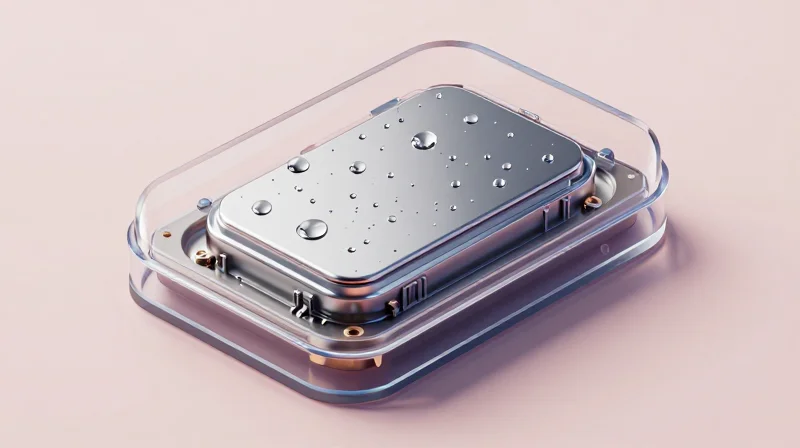
The Engineering Necessity of IP Ratings
Electric wheelchairs frequently operate in diverse outdoor environments where exposure to rain, humidity, mud, and dust is inevitable. For a high-current motor controller, failure to meet adequate Ingress Protection standards often leads to short circuits, accelerated corrosion of power stages, and thermal runaway caused by thermal insulation from trapped dust. An engineering-grade controller must be sealed against these environmental variables to maintain the integrity of its MOSFET drivers and sensitive control circuitry over the intended service life.
IP Rating Classification for Wheelchair Mobility
| IP Rating | Protection Level | Mobility Application |
|---|---|---|
| IP54 | Protected against dust and splashing water | Minimum standard for indoor/limited outdoor use |
| IP65 | Dust-tight and protected against water jets | Standard for robust outdoor electric wheelchairs |
| IP67 | Dust-tight and protected against temporary submersion | High-performance specialized off-road applications |
Frequently Asked Questions
- Is IP65 sufficient for heavy rain conditions?
Yes, IP65 provides protection against low-pressure water jets from any angle, which is generally sufficient for heavy rain exposure. However, prolonged exposure requires proper cable gland sealing to prevent ingress at connection points. - How does potting compound affect IP ratings and thermal management?
Potting compounds significantly improve IP ratings by hermetically sealing the electronics. While this provides superior moisture resistance, it can hinder heat dissipation, necessitating a thermal management strategy that accounts for the thermal resistance of the potting material. - Why is dust protection critical for high-current controllers?
Accumulated dust creates a thermal blanket, reducing the heat sink's efficiency. Furthermore, in humid conditions, conductive dust can cause leakage currents between high-voltage power paths, leading to potential controller failure.
Electromagnetic Compatibility (EMC) and Interference Mitigation

Strategies for Electromagnetic Compatibility (EMC)
Electric wheelchairs integrate high-current switching circuits that inherently produce electromagnetic interference (EMI), which can disrupt onboard clinical monitors or navigation sensors. Mitigation requires a multi-layered approach involving component placement, filtering, and rigorous shielding to meet IEC 60601-1-2 standards.
Key Mitigation Techniques
- Differential Pair Routing
Route high-speed communication signals as differential pairs with matched lengths to maximize noise immunity through common-mode rejection. - Inductive and Capacitive Filtering
Employ Ferrite beads and TVS diodes at all power entry and motor output points to suppress high-frequency transient spikes and prevent conducted emissions. - PCB Layer Stackup Optimization
Utilize a solid ground plane layer immediately beneath the signal layer to minimize current return loop areas, effectively reducing radiated magnetic fields.
Comparison of Shielding Methods
| Shielding Method | Primary Application | Effectiveness | Trade-off |
|---|---|---|---|
| Enclosure Grounding | Chassis/External | High | Weight and Size |
| Faraday Cages | PCB Level | Very High | Heat Dissipation |
| Ferrite Clamps | Cable Interconnects | Moderate | Mechanical Stress |
Common EMC Implementation Questions
- How do switching frequencies impact EMI?
Higher switching frequencies (e.g., >20kHz) move noise into less audible ranges but increase the difficulty of EMI containment due to faster dV/dt transitions; careful snubber circuit design is mandatory. - Should the controller ground be tied to the chassis?
While chassis grounding helps with ESD protection, a dedicated star-grounding topology is preferred to prevent ground loops that could introduce signal noise into sensitive sensor circuits.
Safety-Critical Firmware and Fault Detection

The Necessity of Safety-Critical Firmware
In high-current wheelchair applications, firmware is not merely a control layer; it is the primary safety arbiter. A robust architecture must employ a real-time operating system (RTOS) with deterministic task scheduling to ensure that motor commutation and fault monitoring are never delayed by lower-priority processes. Safety-critical firmware must feature a 'watchdog' implementation that forces the system into a neutral state if the main processing loop hangs, preventing uncontrolled acceleration.
Fault Detection and Mitigation Strategies
| Fault Category | Detection Mechanism | System Response |
|---|---|---|
| Short Circuit | High-speed shunt current monitoring | Instant MOSFET isolation |
| Thermal Overload | NTC thermistor array monitoring | Gradual current limiting followed by shutdown |
| Bus Over-voltage | Regenerative braking energy check | Open-loop coasting or mechanical brake engagement |
| Communication Loss | Heartbeat monitoring via CAN bus | Controlled emergency stop |
Engineering Best Practices for Fail-Safe Design
- How does dual-core redundancy improve reliability?
Using a secondary 'checker' microcontroller to verify the primary controller's calculations ensures that a single point of failure—such as a bit flip in memory—cannot lead to an unintended movement. - What is the role of regenerative braking in safety?
While efficient, regenerative braking must be actively managed by firmware to prevent high voltage spikes from damaging the DC bus or, in worst-case scenarios, causing battery terminal damage. - Why is black-box logging critical?
Non-volatile memory logging of fault codes and 'last-state' telemetry is essential for post-incident analysis and ensures compliance with ISO 14971 risk management standards.
Supply Chain Resilience and Component Longevity
Mitigating Obsolescence Risk in Power Electronics
Electric wheelchairs are medical devices with a long operational lifespan; therefore, the motor controller must be architected using components with established production lifecycles. Engineering teams should prioritize vendors who provide a formal Product Change Notification (PCN) process and maintain long-term availability for critical power MOSFETs, gate drivers, and microcontrollers. Avoiding end-of-life (EOL) surprises is critical to maintaining fleet supportability.
Supply Chain Resilience Strategies
| Strategy | Engineering Benefit | Implementation |
|---|---|---|
| Component Standardization | Reduces reliance on proprietary parts | Use industry-standard SMD packages |
| Vendor Transparency | Early warning of supply disruptions | Require signed PCN/EOL agreements |
| Modular Architecture | Easier replacement of sub-assemblies | Isolate power stage from control logic |
Frequently Asked Questions on Component Longevity
- How can I assess if a manufacturer manages lifecycle risk effectively?
Request their standard operating procedure for PCNs. A mature manufacturer will provide a proactive 12-24 month notice for any component deprecation, allowing time for redesign or Last Time Buy (LTB) options. - Why is component footprint flexibility critical in the design phase?
Designing PCBs with footprint compatibility for multiple manufacturers of the same MOSFET class ensures you are not locked into a single source, providing a buffer against supply chain shocks. - What role does firmware play in hardware longevity?
Abstraction layers in firmware allow you to switch hardware components—such as a new sensor or micro-controller iteration—without requiring a complete rewrite of the motion control algorithms.
Selecting the right motor controller is paramount to building safe, long-lasting electric wheelchairs that users can rely on every day. By prioritizing thermal efficiency, rigorous testing, and strict adherence to safety standards, you can future-proof your design against common failure points. Ready to integrate high-performance electronics into your next project? Contact our engineering team today to discuss custom controller solutions tailored to your mobility specifications.
