
In the world of life-critical medical devices like CPAP machines, the difference between failure and peak performance often resides in the microscopic details of the Printed Circuit Board. Precision motor control demands flawless signal integrity and robust thermal management. This guide explores how rigorous Design for Manufacturing (DFM) standards transform complex PCB concepts into reliable, life-saving hardware.
The Criticality of Precision in CPAP Motor Systems
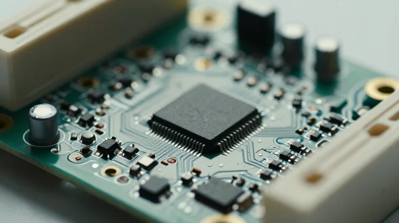
The Clinical Necessity of Motor Precision
In CPAP (Continuous Positive Airway Pressure) systems, the motor controller is not merely a peripheral component; it is the heart of the therapeutic mechanism. The ability of the PCB to regulate motor velocity with sub-millisecond precision directly dictates the consistency of pressure delivery to the patient. Even minor fluctuations in voltage regulation or signal noise can lead to inconsistent airflow, causing patient discomfort, non-compliance, and ineffective treatment of obstructive sleep apnea.
Impact Factors of PCB Design on Device Longevity
| Design Factor | Clinical Impact | Reliability Consequence |
|---|---|---|
| Thermal Management | Minimized noise/vibration | Extended motor bearing life |
| Signal Integrity | Consistent pressure delivery | Reduced component stress |
| EMC/EMI Shielding | Seamless sensor feedback | Prevention of system resets |
Frequently Asked Questions
- Why is PCB noise reduction critical for CPAP motors?
Noise on the motor control lines can cause jitter in the PWM signal, resulting in audible motor whine and inconsistent pressure, which disrupts the patient's sleep cycle. - How does PCB layout affect motor longevity?
Efficient thermal dissipation and clean power distribution via proper PCB layout prevent localized heating, which is the primary cause of electrolytic capacitor failure and motor winding insulation degradation over time.
Advanced Layer Stack-up Configurations
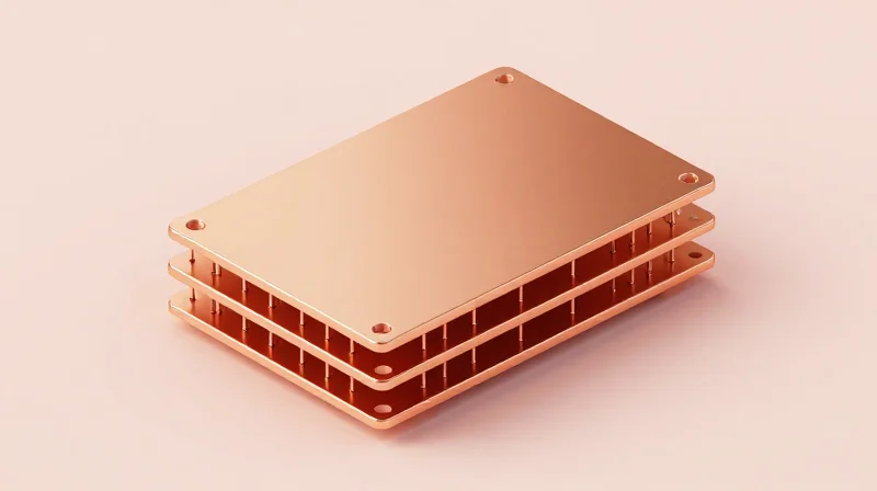
Strategic Layer Stack-up for High-Speed Motor Control
For CPAP motor control circuits, the PCB stack-up is the primary defense against electromagnetic interference (EMI) and power instability. A minimum six-layer board configuration is recommended to provide dedicated solid ground planes, which are essential for referencing high-speed switching signals used in Field Oriented Control (FOC) motor drivers. By placing high-frequency signal layers adjacent to ground planes, designers can minimize loop areas, significantly reducing radiated emissions—a critical requirement for medical compliance.
Recommended Stack-up Characteristics
| Layer Type | Primary Function | DFM Consideration |
|---|---|---|
| Top Signal | Low-level sensing/logic | Short trace paths to minimize inductance |
| Ground Plane | Return current/shielding | Solid copper; no splits in high-speed zones |
| Power Plane | Motor bus voltage distribution | Wide traces/planes for current handling |
| Bottom Signal | Control feedback/I/O | Avoid running sensitive signals under motor drivers |
Optimizing Power Integrity for Motor Drivers
Motor drivers in CPAP devices generate high transient currents during PWM switching. To prevent voltage ripple from propagating into sensitive sensor feedback lines, designers must utilize a low-impedance power distribution network (PDN). This is achieved by increasing the copper thickness on internal power layers and placing high-frequency decoupling capacitors as close to the driver ICs as physically possible.
Frequently Asked Questions on Stack-up Design
- Why is a 6-layer stack-up preferred over 4-layer for motor controllers?
A 6-layer stack-up allows for independent ground and power planes, which provides superior shielding for sensitive feedback signals compared to the shared planes in a 4-layer design. - How does stack-up design impact thermal management?
Internal copper planes act as heat spreaders. By using thicker copper (2 oz or higher) on internal layers directly beneath power components, you can effectively move heat away from the silicon into the board substrate. - Is it safe to use split ground planes for digital and analog sections?
In high-speed motor control, split planes often introduce more EMI issues than they solve. A unified solid ground plane with careful component partitioning is generally the professional standard.
High-Speed Signal Integrity and Trace Routing
Achieving reliable operation in CPAP motor control requires a disciplined approach to trace routing that separates high-current PWM motor drive lines from sensitive low-voltage feedback signals. In medical applications, where motor jitter can lead to inconsistent pressure delivery and audible noise, the design must prioritize signal integrity through controlled impedance and noise-rejection strategies.
Mitigating Cross-talk Between Power and Sense Lines
Inductive cross-talk is the primary adversary in motor control PCB layout. Because motor drivers switch high currents at significant frequencies, the associated electromagnetic fields can easily couple into sensitive Hall-effect sensors or back-EMF monitoring lines. Designers must enforce physical isolation, utilizing guard traces or dedicated ground plane stitching to dampen unwanted coupling between the drive and sense signals.
| Routing Parameter | Recommended Practice | Medical Benefit |
|---|---|---|
| Trace Separation | Minimum 3x Trace Width | Reduced Inductive Coupling |
| Differential Pairs | Strict Length Matching | Elimination of Jitter |
| Reference Planes | Solid Ground Under Signals | Lower Return Path Impedance |
Best Practices for Trace Routing
- How should high-current PWM traces be routed?
Route PWM traces on internal layers between solid reference planes to contain EMI, and keep loop areas as small as possible by using adjacent ground return paths. - What is the optimal approach for sensitive feedback signals?
Keep analog sensor traces as short as possible and use a differential routing scheme to provide inherent common-mode noise rejection against switching transients. - Does trace width impact thermal reliability in CPAP devices?
Yes; use an IPC-2152 compliant calculator to size motor drive traces, ensuring copper weight and width prevent excessive heat rise which could affect component accuracy over time.
Managing Jitter via Impedance Control
For high-speed communication buses (such as SPI or I2C) communicating with the motor controller, maintaining controlled impedance is vital. Mismatched impedance creates signal reflections that lead to timing jitter, potentially corrupting control instructions. Designers should define stack-up impedance requirements early in the fabrication process and verify that trace geometries are strictly controlled across the entire signal path.
Thermal Management Strategies for Small Form Factors
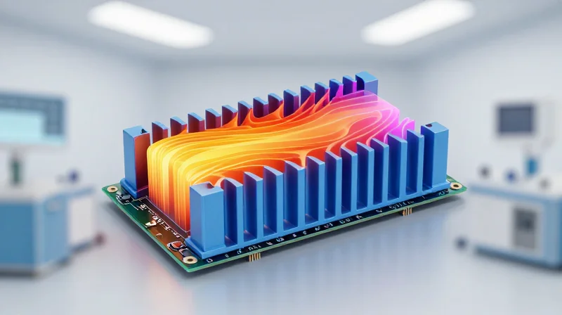
Thermal Dissipation in Compact Medical Enclosures
In CPAP devices, limited airflow and high-density packaging necessitate a proactive thermal design strategy. Because heat significantly degrades electrolytic capacitor longevity and can cause motor control MOSFETs to enter thermal throttling, engineers must treat the entire PCB as a heat sink. By employing a multi-layered approach to thermal distribution, designers can maintain stable junction temperatures without the need for active cooling components that would otherwise increase device footprint and noise.
Core Thermal Mitigation Techniques
- Strategic Copper Pours
Utilize massive copper pours connected to high-heat components to act as thermal mass; connect these to the internal ground planes via localized thermal stitching to effectively spread heat across the board surface. - Thermal Via Arrays
Implement dense grids of thermal vias directly beneath power MOSFETs and motor drivers, ensuring they tie into multiple internal planes to provide a low-resistance path for heat dissipation to the bottom of the PCB. - Component Partitioning
Place heat-generating motor drive electronics away from thermally sensitive sensors or high-precision feedback circuitry, creating distinct 'thermal zones' to prevent local temperature spikes from causing signal drift.
Comparison of Thermal Management Techniques
| Strategy | Primary Benefit | DFM Consideration |
|---|---|---|
| Copper Pours | Increased surface area | Ensure sufficient solder mask clearance |
| Thermal Vias | Vertical heat transfer | Cap/plug to prevent solder wicking |
| Component Zoning | Reduced localized stress | Requires early layout planning |
When designing for fabrication, ensure that thermal vias are specifically noted as 'capped' or 'filled' in the DFM documentation. Failure to address via plugging can result in solder wicking during assembly, leading to unreliable solder joints that compromise the structural and thermal integrity of the motor controller under continuous operation.
DFM Standards for Medical-Grade Reliability
IPC Standards and Reliability Benchmarking
For CPAP motor control systems, PCB fabrication must transition from standard consumer-grade processes to IPC Class 3 standards. This tier mandates heightened scrutiny regarding annular ring requirements, plating thickness, and dielectric integrity to ensure that the device functions reliably throughout its intended lifespan, especially under the continuous vibration inherent in motor operations.
| Parameter | Commercial Standard | Medical-Grade (IPC Class 3) |
|---|---|---|
| Min. Annular Ring | 50 microns | 100+ microns |
| Copper Plating | 20 microns (avg) | 25 microns (min) |
| Vias | Standard drill | Plugged/Filled for reliability |
DFM Protocols for Field Stability
Designing for field stability in medical motor control requires specific mechanical and chemical considerations during the DFM phase. By mitigating risks during fabrication, designers prevent catastrophic failures that could lead to device downtime or patient harm.
- Soldermask Selection
Use high-CTI (Comparative Tracking Index) soldermask materials to prevent electrochemical migration between high-voltage motor traces in humid clinical environments. - Finish Reliability
Prefer ENIG or ENEPIG over HASL for superior planarity and to prevent the risk of solder leaching or whisker formation that can compromise long-term connectivity. - Thermal Cycling Mitigation
Utilize balanced copper foil distribution across layers to minimize internal stresses and prevent PCB bowing or delamination during the motor's operating temperature cycles.
Validation and Compliance
Finalizing the DFM package requires thorough documentation. This includes providing precise Gerber files, stack-up definitions, and IPC-standard fabrication notes. Ensuring your CM (Contract Manufacturer) utilizes automated optical inspection (AOI) and X-ray analysis for internal layer verification is not merely a recommendation, but a mandatory checkpoint for medical-grade motor control assembly.
Quality Control and Testing Protocols
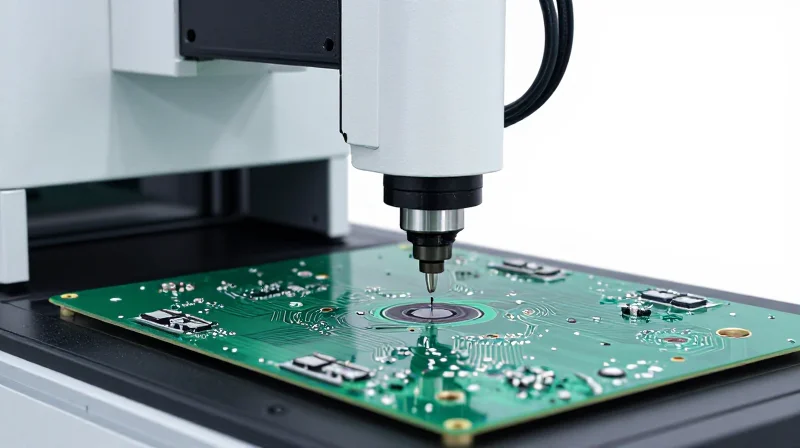
Multi-Tiered Testing Strategy
For CPAP motor control boards, achieving medical-grade reliability necessitates a multi-tiered inspection approach. By integrating automated optical inspection (AOI) with flying probe testing and functional circuit testing (FCT), manufacturers can identify defects ranging from solder bridges to intermittent signal latency before the assembly leaves the facility.
| Method | Primary Focus | Medical Application |
|---|---|---|
| AOI | Component presence and alignment | Detecting missing SMT components |
| Flying Probe | Electrical connectivity | Shorts in high-density motor driver circuits |
| ESS | Thermal/vibration stress | Simulating field longevity in home settings |
Environmental Stress Screening (ESS)
Environmental Stress Screening is critical for medical devices that operate in home environments. CPAP motors are subject to varying ambient temperatures and vibration profiles. ESS forces 'infant mortality' failures to occur during the manufacturing phase rather than during critical patient therapy by subjecting the populated PCBs to temperature cycling and burn-in processes.
Key Quality Assurance FAQs
- Why is FCT preferred over ICT for CPAP controllers?
Functional Circuit Testing (FCT) powers the board to simulate motor operation under load, which is essential for validating the PWM signal integrity that In-Circuit Testing (ICT) might miss. - How does AOI mitigate risk in miniaturized layouts?
AOI utilizes high-resolution cameras to verify micro-solder joints in dense layouts where manual inspection by human operators would be susceptible to fatigue and error. - What is the role of traceability in this process?
Every testing stage must be logged with board-level serialization to ensure that if a field failure occurs, the specific manufacturing lot and test results can be audited immediately.
Compliance, Traceability, and Regulatory Alignment
Regulatory Alignment and Traceability in PCB Fabrication
In the context of medical devices like CPAP machines, the PCB serves as a critical component where failure could jeopardize patient safety. Compliance with ISO 13485 and FDA 21 CFR Part 820 demands that manufacturers implement comprehensive traceability throughout the entire supply chain. This involves tracking every component lot number, PCB panel ID, and assembly batch to ensure that any potential field failure can be traced back to its root cause, fulfilling mandatory recall and post-market surveillance requirements.
Essential Documentation for Medical Audits
| Requirement | Purpose | Frequency |
|---|---|---|
| Certificate of Conformance | Verification of raw material quality | Per batch |
| Process FMEA | Risk identification and mitigation | Pre-production |
| Device History Record (DHR) | Complete manufacturing traceability | Per unit/lot |
Frequently Asked Questions on Compliance
- How does ISO 13485 impact PCB material selection?
ISO 13485 mandates strict control over raw materials. You must ensure all laminate materials, solder pastes, and fluxes are sourced from approved suppliers with verifiable Certificates of Analysis (COA) to prevent contamination and process drift. - What is the role of the Device History Record in DFM?
The DHR is a living document that records the production history, including test results and non-conformance reports. During the DFM phase, you must design board features—such as serialization markers—that simplify automated data collection for the DHR. - Why is lot-level traceability critical for motor control boards?
Motor control boards often use high-performance MOSFETs and passive components subject to strict tolerances. Traceability ensures that if a specific lot of semiconductors shows premature degradation, you can precisely identify and replace affected CPAP units before patient harm occurs.
Achieving medical-grade excellence is a continuous process of refining design, material selection, and fabrication oversight. By integrating these DFM strategies, you ensure that your motor control systems perform with uncompromising precision under any condition. Ready to optimize your next project? Contact our engineering team today to discuss your specific PCB requirements and accelerate your time to market.
