
In the fast-evolving landscape of portable medical technology, the pressure to shrink form factors while maintaining hospital-grade reliability has never been greater. Designers of oxygen concentrators face a delicate balancing act: how to package high-performance power electronics and sensitive sensors into a compact, thermal-stressed enclosure without compromising patient safety. This guide explores the critical DFM strategies required to navigate these engineering hurdles effectively.
Thermal Management in Confined Enclosures
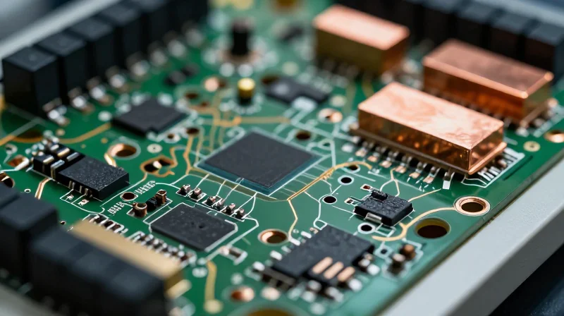
Optimizing Heat Dissipation in High-Density Assemblies
In the confined, battery-operated chassis of a portable oxygen concentrator, thermal density is the primary driver of device failure. High-density PCB design must prioritize a low-impedance thermal path from heat-generating power stages—such as compressor motor controllers and microprocessors—to the device’s structural heat sink. Designers should employ a 'thermal zoning' methodology, isolating sensitive RF and sensing components from high-wattage power electronics to prevent localized hotspots that degrade component lifespan and sensor accuracy.
Strategic Component Placement and Thermal Via Arrays
Thermal via arrays act as the bridge between component pads and internal ground planes. For maximum efficiency, use arrays with a pitch of 0.8mm to 1.0mm, plated with copper to a minimum thickness of 25 micrometers. These vias must be tied directly to the largest copper pour on the internal layer to maximize spreading resistance reduction.
| Strategy | Implementation Priority | Thermal Impact |
|---|---|---|
| Thermal Vias | High | Reduces junction-to-board resistance by 40-60% |
| Component Zoning | Critical | Prevents thermal feedback loops for sensors |
| Copper Weight | Medium | Improves lateral heat spreading on outer layers |
Material Selection for Enhanced Reliability
Standard FR-4 is often insufficient for high-density oxygen concentrator boards. Upgrading to high-Tg (glass transition temperature) laminates, such as those with a Tg of 170°C or higher, prevents board warpage during high-current operations. Furthermore, incorporating thermally conductive prepregs can improve the overall board bulk thermal conductivity, effectively turning the PCB into a passive radiator.
- How does via-in-pad technology affect board thermal performance?
Via-in-pad technology allows for a direct thermal connection from the component thermal pad to the internal planes, drastically lowering thermal resistance compared to traditional dog-bone routing. - Is internal copper thickness more important than external?
While external copper helps with component cooling, internal layers act as the primary heat spreader. A minimum of 2oz copper on internal planes is recommended for high-density power applications. - What is the role of the solder mask in thermal design?
Standard solder masks act as thermal insulators; for critical power components, designers should consider opening the mask or using thermally conductive, specialized coatings to improve heat transfer to the ambient air.
Signal Integrity and Electromagnetic Compatibility (EMC)
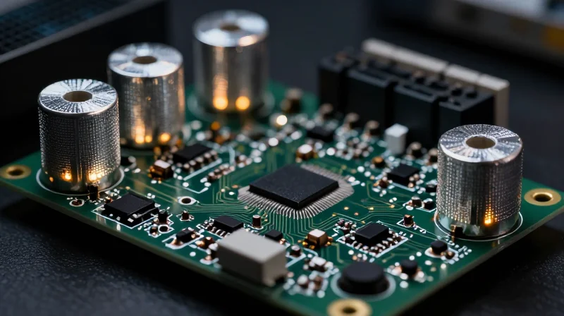
Mitigating EMI in High-Density Medical Systems
Portable medical oxygen concentrators rely on high-precision sensors that are extremely susceptible to electromagnetic interference (EMI). In high-density PCB layouts, the proximity of switching power supplies to sensitive analog front-ends creates a significant risk of signal degradation. Designers must prioritize rigid return-path control and layered stackup strategies to prevent crosstalk and radiated emissions.
Best Practices for Layout Integrity
- Continuous Ground Planes
Always prioritize an unbroken reference plane directly beneath signal layers to minimize loop area, which is the primary driver of radiated EMI. - Differential Pair Coupling
Maintain tight coupling and equal length matching for high-speed differential pairs to ensure common-mode noise cancellation. - Partitioning Strategies
Physically isolate noisy switching power supply circuitry from sensitive physiological sensor amplifiers using 'moats' or split-plane techniques if strictly necessary, while ensuring low-impedance bridge connections.
| Noise Mitigation Technique | Effectiveness | Implementation Priority |
|---|---|---|
| Stitching Vias | High | Critical |
| Guard Traces | Moderate | Low |
| Decoupling Capacitors | High | Critical |
| Board-Level Shielding | Extreme | Secondary |
Standardized Filtering Implementation
/* Recommended footprint for EMI suppression ferrite beads on sensitive lines */
const footprint = { type: 'ferrite_bead', package: '0402', position: 'source_load' };
// Ensure placement is within 2mm of the connector entrance
By integrating these DFM rules into the early design phase, engineers can ensure that the compact form factor of a portable oxygen concentrator does not compromise the reliable transmission of sensitive patient vitals. Proactive EMI management is not merely a compliance requirement but a fundamental aspect of device safety.
Component Selection for Mission-Critical Reliability
Component Selection Criteria for Medical-Grade Reliability
In the context of portable oxygen concentrators, component selection extends beyond basic electrical functionality, necessitating a lifecycle approach that anticipates thermal cycling, mechanical shock, and long-term storage stability. Designers must prioritize AEC-Q or industrial-grade components with extended temperature ratings to mitigate the risks associated with the high-density heat accumulation common in compact enclosures.
| Requirement Category | Selection Strategy | DFM Impact |
|---|---|---|
| Passive Components | Use X7R/C0G dielectrics for stability | Reduces leakage current in dense layouts |
| Connectors | Gold-plated with locking mechanisms | Prevents fretting corrosion under vibration |
| Active ICs | Grade 1 or 2 automotive qualification | Ensures reliable operation in -40C to 125C range |
Mitigating Failure Modes in Portable Environments
- How do you account for mechanical shock in portable units?
Prioritize surface-mount components with robust termination designs and implement localized potting or underfill for BGA packages to redistribute mechanical stress away from the solder joints. - What is the critical constraint for electrolytic capacitors?
Select solid-polymer capacitors over wet-electrolyte types to eliminate the risk of dry-out failure during extended operation cycles, which is critical for ISO 13485 maintenance schedules. - Does component height matter in high-density DFM?
Yes; minimizing vertical profiles reduces the internal airflow impedance, allowing for more consistent convective cooling and reducing local hotspots that accelerate component degradation.
Finally, supply chain transparency is a component selection rule in itself. Ensuring traceability down to the wafer level is essential for complying with medical device reporting (MDR) regulations, making it mandatory to vet suppliers for their long-term component availability and PCN (Product Change Notification) policies.
Layer Stack-up Optimization for Compact Form Factors
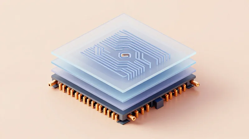
Strategic HDI Stack-up Architecture
For portable oxygen concentrators, minimizing board thickness without compromising electrical performance is achieved through symmetrical HDI stack-ups. Utilizing laser-drilled microvias allows for high-density routing on outer layers while reserving internal layers for dedicated ground and power planes, significantly reducing the overall footprint.
| Parameter | Standard Stack-up | HDI Optimized Stack-up |
|---|---|---|
| Board Thickness | 1.6mm | 0.8mm - 1.0mm |
| Via Technology | Through-hole | Stacked/Staggered Microvias |
| Routing Density | Baseline | 3x to 5x increase |
Balancing Power Integrity and Board Mass
To maintain signal stability in a compact device, implement 'core-less' or 'thin-core' construction techniques. By placing power planes closer to the signal layers, you increase inter-plane capacitance, which effectively suppresses switching noise and stabilizes voltage delivery to high-speed sensor processors.
Frequently Asked Questions on HDI Design
- How does layer symmetry affect board warping?
In thin, portable boards, asymmetrical stack-ups often lead to thermal-mechanical stress. Maintaining a symmetrical stack-up relative to the neutral axis is critical to prevent warping during lead-free reflow processes. - When should I transition from buried vias to microvias?
Transition to microvias when your BGA pitch drops below 0.5mm. This shift allows for 'via-in-pad' designs, which free up critical routing channels on the inner layers. - How do I manage heat in a high-density stack-up?
Integrate copper-filled thermal via arrays directly beneath heat-generating power ICs, connecting them to internal ground planes that act as primary heat spreaders.
DFM Constraints for Automated Assembly
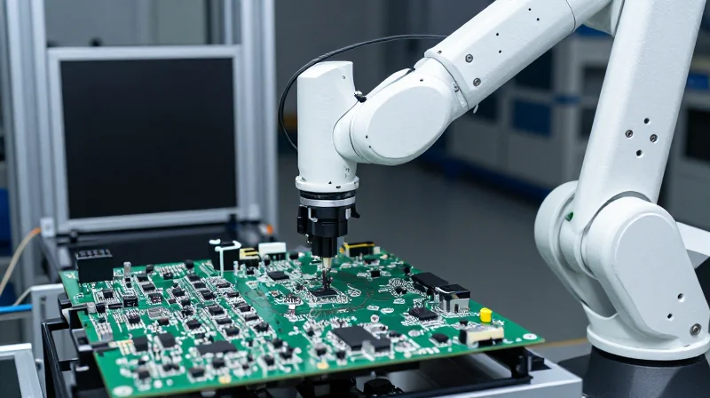
Optimizing DFM Constraints for Automated Assembly
Automated assembly for high-density portable medical devices demands extreme precision in board design to accommodate high-speed SMT lines. By implementing stringent DFM constraints—specifically regarding pad geometries, fiducial precision, and component clearance—manufacturers can significantly reduce defect rates such as tombstoning, solder bridging, and component misalignment, which are critical in mission-critical oxygen delivery systems.
Critical DFM Parameter Benchmarks
| Design Parameter | Recommended Constraint | Rationale |
|---|---|---|
| Fiducial Clearance | 3.0mm minimum radius | Ensures optical recognition for high-speed pick-and-place cameras. |
| Component Spacing | 0.5mm minimum | Permits rework access and prevents solder bridging on fine-pitch ICs. |
| Pad-to-Solder Mask | 0.05mm | Controls solder flow to prevent shorts during reflow. |
| Via-in-Pad | Filled and Capped | Prevents solder wicking away from the component lead. |
Frequently Asked Questions on Assembly Constraints
- Why is global fiducial placement critical in this context?
Global fiducials allow the automated vision system to align the board correctly within the SMT machine coordinate system, which is essential when dealing with high-density components where placement accuracy must be within microns. - How does PCB thickness influence automated assembly stability?
In portable devices, thinner boards may flex under the pressure of vacuum nozzles, causing placement errors; therefore, jig support or rigid-flex staging must be accounted for in the DFM phase. - Is Solder Mask Defined (SMD) or Non-Solder Mask Defined (NSMD) preferred?
For fine-pitch BGAs used in medical concentrators, NSMD pads are generally preferred as they provide superior mechanical anchoring for solder joints during the thermal expansion cycles of portable operation.
Rigorous Testing and Validation Protocols
In portable life-support hardware like oxygen concentrators, failure is not an option. Testing protocols must be established early in the DFM phase, ensuring that test points are accessible, signal integrity is verifiable under load, and firmware-level diagnostics confirm sensor calibration accuracy. Validation must occur prior to final enclosure sealing to prevent costly rework.
In-Circuit Testing (ICT) Strategy
For HDI designs, physical space for test pads is often at a premium. Designers must balance the density of components with the need for adequate bed-of-nails access. By prioritizing critical power rails and low-speed signal monitoring during the design phase, you ensure that manufacturing defects—such as solder bridges, open circuits, or incorrect component values—are caught before reaching the final assembly stage.
| Testing Type | Primary Objective | Design Requirement |
|---|---|---|
| In-Circuit Test (ICT) | Verify connectivity/shorts | Test point pads (0.035" min) |
| Flying Probe | Prototypes/Low Volume | Access to all nets preferred |
| Functional Test (FCT) | Confirm device operation | Programming headers/I/O pins |
Validation Protocol FAQ
- How can I maintain testability in a 10-layer HDI stack-up?
Utilize micro-vias for signals but ensure that critical nets are routed to external layers or dedicated test pads for probing. Avoid placing test points underneath high-profile components. - Why is functional testing mandatory after ICT?
ICT verifies the physical integrity of the PCB, but functional testing confirms that the oxygen concentration algorithms and sensor feedback loops are performing within ISO 13485 clinical thresholds. - What is the best way to handle non-conductive testing?
For sensitive oxygen sensors, use non-contact optical inspection or JTAG boundary scanning to verify communication integrity without physically stressing delicate sensor membranes.
Verification Code Snippet
def validate_oxygen_sensor_signal(signal_input, threshold=0.05):
    # Ensure signal voltage is stable for clinical operation
    if abs(signal_input - EXPECTED_STABLE_VOLTAGE) < threshold:
        return True
    return False
Compliance and Regulatory Documentation
Documentation Strategy for Regulatory Compliance
Regulatory bodies, including the FDA (21 CFR Part 820) and European notified bodies (MDR 2017/745), require exhaustive evidence that design intent is preserved throughout the manufacturing lifecycle. For high-density portable medical devices, this requires a closed-loop DFM documentation system where every manufacturing variance, material change, and design rule exception is formally recorded and validated against initial performance specifications.
| Documentation Category | Key Requirement | Regulatory Significance |
|---|---|---|
| Design History File (DHF) | DFM constraint logs | Proof of intent and safety |
| Device Master Record (DMR) | Assembly drawings/BOM | Production consistency |
| Process Validation (IQ/OQ/PQ) | SMT parameter logs | Reliability under load |
Managing Design Traceability in HDI Assemblies
Traceability in complex oxygen concentrator PCBs is not merely administrative; it is a clinical requirement. Advanced DFM records must link specific design constraints (such as micro-via aspect ratios or solder paste stencil modifications) to the final serialized unit. This ensures that in the event of a field failure, engineers can determine whether the root cause lies in the design, the board fabrication, or the assembly process.
- How do DFM records assist in a clinical audit?
Detailed DFM records demonstrate to auditors that the manufacturer has identified potential failure modes during the design phase and implemented specific mitigation strategies, such as clearance buffers and thermal management protocols. - Why is material traceability critical for HDI?
High-density interconnect boards often utilize specialized laminates for thermal stability; documenting lot-specific material characteristics ensures compliance with biocompatibility and shelf-life requirements in the final medical device. - What is the impact of post-design DFM changes?
Any modification to DFM constraints post-design must trigger a formal change control process, including a risk analysis update, to ensure the board remains compliant with its initial regulatory submission.
Automating Compliance Reporting
To minimize human error in documentation, high-reliability assembly houses should leverage automated reporting scripts that extract DFM rule-check summaries directly from the EDA environment. These automated reports should be appended to the Device History Record (DHR) to provide an audit-ready trail of the design's evolution from concept to production release.
Successfully engineering medical-grade electronics demands a proactive approach to DFM that integrates thermal, electrical, and mechanical requirements from day one. By adhering to these rigorous standards, you minimize field failure risks and ensure your portable oxygen systems deliver life-saving performance. Contact our engineering team today to audit your current PCB designs and accelerate your product time-to-market.
