
In the high-stakes world of medical mobility, the reliability of a motor controller can literally define a user's independence. As engineers, balancing high-ampere power loads with strict space constraints is a constant challenge. This guide dives into the advanced DFM strategies required to ensure your PCB designs are not only functional but resilient enough for life-critical applications.
The Anatomy of High-Current PCB Failure
The Anatomy of High-Current PCB Failure
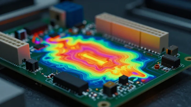
In the context of electric wheelchair motor controllers, PCBs are subjected to repetitive high-amperage transients and demanding thermal cycling. Failure is rarely instantaneous; it is typically the result of long-term material degradation initiated by localized hotspots, differential thermal expansion, and electromigration. Identifying these failure modes during the design phase is paramount to ensuring the safety and longevity of medical mobility hardware.
Primary Failure Mechanisms
| Failure Mechanism | Root Cause | Resulting Damage |
|---|---|---|
| Thermal Runaway | Excessive trace resistance | Substrate delamination and charring |
| Interconnect Fatigue | Cyclic mechanical stress | Solder joint cracking and fracture |
| Electromigration | High current density | Conductive filament growth and shorting |
Diagnostic Insights and FAQs
- Why do high-current traces often delaminate?
Delamination is frequently caused by the mismatch in Coefficient of Thermal Expansion (CTE) between the copper traces and the FR-4 substrate, compounded by high heat that weakens the epoxy resin. - How does vibration contribute to controller failure?
Electric wheelchairs experience constant micro-vibrations; these cycles cause mechanical fatigue in rigid solder joints, eventually leading to intermittent connectivity or total electrical open circuits. - Is board thickness a factor in thermal management?
Yes, thinner substrates can improve heat dissipation, but thicker boards provide better structural rigidity to prevent board flexing, which is critical for protecting heavy power components.
Trace Width Optimization and Current Carrying Capacity
Applying IPC-2152 Standards for Thermal Stability
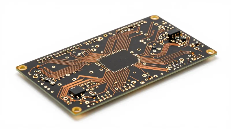
In high-current motor controller design, trace dimensions must be calculated based on maximum allowable temperature rise rather than simple DC resistance. Unlike outdated IPC-2221 models, IPC-2152 provides a more nuanced approach by considering the PCB's thermal environment, including copper weight, trace geometry, and heat sinking capacity. By accurately calculating the cross-sectional area, designers can balance form factor constraints with the thermal headroom required for reliable, continuous operation in demanding mobility environments.
Impact of Copper Weight on Current Capacity
| Copper Weight (oz) | Thickness (mm) | Relative Current Capacity | Recommended Application |
|---|---|---|---|
| 1.0 | 0.035 | Baseline | Control Logic & Signaling |
| 2.0 | 0.070 | ~1.6x | Intermediate Power Stages |
| 3.0 | 0.105 | ~2.2x | Primary Motor Drive Paths |
Strategies for Trace Width Optimization
Optimizing trace width is a multi-dimensional challenge involving board space limitations and thermal dissipation requirements. To achieve long-term durability in wheelchair controllers, designers should implement the following strategies:
- Redundancy and Layer Stacking
Utilize parallel traces on adjacent layers connected by dense thermal vias to increase effective cross-sectional area without exceeding physical footprint constraints. - Localized Heat Sinking
Increase copper pour regions around high-current traces to act as integrated heat sinks, lowering the localized thermal resistance and keeping traces well below their glass transition temperature (Tg). - Solder Mask Minimization
In critical power paths, consider exposing copper traces and reinforcing them with additional solder or bus bars to significantly lower resistance and improve thermal shedding.
Advanced Thermal Management and Copper Stack-ups
Advanced Thermal Management and Copper Stack-ups
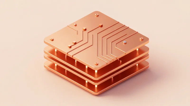
Effective thermal management in electric wheelchair motor controllers requires a holistic approach that combines high-mass conductive pathways with low-impedance thermal paths. When handling sustained currents exceeding 50A, standard 1oz copper is insufficient; instead, designers must utilize heavy copper (2oz to 4oz) and integrated thermal relief structures to ensure long-term reliability in high-vibration medical environments.
Optimizing Thermal Via Arrays
Thermal vias serve as the primary conduit for transferring heat from surface-mount MOSFETs to internal ground planes or external heatsinks. To maximize efficiency, developers should adhere to the following layout principles: (1) use a tight pitch (typically 0.8mm to 1.0mm) to minimize thermal resistance, (2) prefer through-hole vias that are filled and capped to prevent solder wicking, and (3) increase copper plating thickness within the barrel of the via to improve thermal conductivity.
| Feature | Design Best Practice | Performance Impact |
|---|---|---|
| Copper Weight | 2oz - 4oz internal/external | Reduces I2R heating by lowering resistance |
| Thermal Vias | 0.3mm diameter, 0.8mm pitch | Decreases junction-to-ambient thermal resistance |
| Stack-up Geometry | Symmetric layer distribution | Prevents board warping during thermal cycling |
Frequently Asked Questions
- Why is symmetric copper stack-up critical?
Asymmetric copper distribution leads to uneven thermal expansion, causing the PCB to bow or twist during operation, which can crack solder joints on large power components. - Does PCB finish affect thermal performance?
While minimal, high-emissivity surface finishes or heavy-duty conformal coatings can aid in radiative heat transfer; however, conductive cooling through the board remains the primary focus. - Should thermal vias be left open or filled?
Always specify copper-filled and capped vias (IPC-4761 Type VII). Open vias often suffer from solder wicking, resulting in voiding beneath components that dramatically degrades thermal dissipation.
Mitigating EMI in Motor Drive Circuits

Strategic Layer Stacking and Plane Assignment
EMI performance begins with the PCB stack-up. For motor controllers, a minimum four-layer configuration is mandatory to maintain signal integrity and contain radiation. Placing high-speed control traces on inner layers sandwiched between solid ground planes acts as an effective Faraday cage. This configuration reduces the loop area of critical signals and minimizes common-mode noise propagation across the board.
Decoupling Capacitor Placement Strategies
To suppress switching noise effectively, decoupling capacitors must be placed in immediate proximity to the MOSFET power stages. Utilizing a multi-tier approach—combining low-ESR ceramic capacitors for high-frequency suppression with bulk electrolytic capacitors for energy storage—prevents voltage ripple from manifesting as radiated EMI.
| EMI Mitigation Strategy | Implementation Priority | Key Benefit |
|---|---|---|
| Solid Ground Planes | Critical | Minimized loop inductance |
| Component Shielding | High | Block radiated emissions |
| Decoupling Proximity | Critical | Suppress transient noise spikes |
| Differential Routing | Medium | Improved noise immunity |
Frequently Asked Questions
- Why is layer stack-up critical for motor drive circuits?
Improper stacking creates large inductive loops that act as antennas for switching noise generated by high-frequency PWM signals in motor controllers. - How does board-level shielding affect thermal performance?
While shielding reduces EMI, it can trap heat. Use thermal interface materials to bridge the shield to the heatsink, ensuring that EMI mitigation does not compromise thermal dissipation. - Can trace width influence EMI?
Yes, overly wide traces used for high-current paths can inadvertently increase coupling area. Maintaining tight return paths directly beneath power traces is more effective for EMI control than trace width alone.
Ensuring Solder Joint Integrity
Optimizing Pad Geometry for High-Reliability Interconnects
In medical-grade motor controllers, solder joints are subjected to consistent mechanical stress and thermal cycling. To minimize fracture risk, designers must transition from standard surface-mount footprints to reinforced land patterns that distribute mechanical loads effectively across the PCB substrate.
Solder Mask and Pad Clearance Standards
Proper control of solder mask define (SMD) versus non-solder mask define (NSMD) pads is essential. For high-current power components, NSMD pads provide a larger copper bonding area, which improves adhesion to the laminate during high-vibration events.
| Feature | Recommended Practice | Benefit |
|---|---|---|
| Pad Definition | NSMD (Non-Solder Mask Defined) | Enhanced mechanical anchor for vibration resistance |
| Mask Clearance | 50um - 75um | Prevents mask encroachment onto the soldering surface |
| Fillet Design | Concave meniscus | Reduces stress concentrations at the component lead |
Frequently Asked Questions on Joint Integrity
- How does vibration affect solder joint lifespan?
Constant vibration in wheelchair motor controllers causes cyclical mechanical fatigue, leading to micro-cracks in the intermetallic compound layer, which eventually propagate to complete failure if the pad is not properly supported. - Why is solder mask clearance critical for power components?
Insufficient clearance allows the solder mask to overlap the copper pad, creating uneven wetting surfaces that lead to stress risers; precise 50-75 micron clearance ensures uniform solder flow and robust joint formation. - Is lead-free solder viable for high-vibration medical devices?
While SAC305 is the industry standard, it can be brittle under high shock; engineers should consider conformal coating or underfill processes to mechanically reinforce the components in high-vibration environments.
Material Selection for Power Density
Material Selection for Power Density
In high-current motor controllers, standard FR-4 laminates often fail due to excessive heat generation, leading to mechanical warping and dielectric breakdown. To ensure reliable performance under continuous heavy loads, engineers must transition to high-glass transition temperature (Tg) substrates and metal-core or ceramic-filled thermal laminates. These materials maintain mechanical rigidity at elevated operating temperatures, preventing pad lifting and trace separation during cyclic thermal stress.
Comparing PCB Substrate Performance
| Material Type | Tg Rating | Thermal Conductivity | Ideal Application |
|---|---|---|---|
| Standard FR-4 | 130-140C | 0.25 W/mK | Logic-only circuits |
| High-Tg FR-4 | 170-180C | 0.30 W/mK | General power electronics |
| Thermal Laminates | >200C | 2.0 - 5.0 W/mK | High-current motor stages |
Key Considerations for Material Selection
- Why is the Glass Transition Temperature (Tg) so critical?
The Tg defines the point where the polymer changes from a hard, glassy state to a rubbery, soft state. Exceeding this limit causes expansion in the Z-axis, which frequently leads to barrel cracking in copper-plated vias. - How do thermally conductive laminates improve power density?
These materials incorporate ceramic fillers that effectively bridge the gap between heat-generating components and the mechanical chassis or heatsinks, allowing for smaller form-factor designs without sacrificing reliability. - Does material choice affect high-frequency motor noise?
Yes, high-Tg materials often exhibit more stable dielectric constants across varying temperatures, which helps maintain predictable signal integrity and minimizes EMI in high-speed switching circuits.
Design for Assembly (DFA) Considerations
Streamlining Automated Assembly for Power Electronics
Design for Assembly (DFA) in high-current applications focuses on reducing handling complexity and maximizing first-pass yield during Surface Mount Technology (SMT) processes. By standardizing component footprints and prioritizing top-side assembly, manufacturers can significantly reduce the need for double-sided reflow, which is often a source of thermal stress and assembly defects in power-dense designs.
DFA Strategic Best Practices
- Component Orientation
Align all polarized components in the same direction to simplify automated optical inspection (AOI) programming and reduce picking errors during high-speed placement. - Thermal Relief Standardization
Use consistent thermal relief patterns for high-current copper pours to ensure uniform heating during wave or selective soldering, preventing cold joints on power pins. - Panelization Efficiency
Optimize board dimensions for panel utilization while ensuring sufficient routing for thermal break-away tabs, which prevents mechanical stress during board separation.
Design Trade-offs: Through-Hole vs. Surface Mount
| Feature | Surface Mount (SMT) | Through-Hole (THT) |
|---|---|---|
| Automation Cost | Low (Standardized) | High (Specialized) |
| Mechanical Bond | Moderate | Superior (Vibration Resistant) |
| Assembly Speed | Very High | Low |
For electric wheelchair motor controllers, mechanical durability is non-negotiable. While SMT is preferred for its production efficiency, high-mass components like large electrolytic capacitors or heavy inductors should be secured with underfill or mechanical adhesive to meet IEC vibration standards, effectively bridging the gap between SMT process speed and THT-level ruggedness.
Validating Reliability Through Accelerated Testing
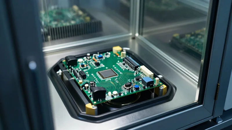
Validating Reliability Through Accelerated Testing
Before transitioning to mass production, high-current PCB assemblies must undergo rigorous accelerated life testing to confirm their durability under the demanding conditions of medical mobility applications. For electric wheelchair motor controllers, this primarily involves thermal cycling and power-load testing to simulate years of operation in an intensified time frame, identifying failure modes—such as CTE mismatch, solder joint fatigue, or component overheating—before they impact end-users.
Accelerated Testing Methodologies
| Test Method | Primary Failure Mechanism | Targeted Design Area |
|---|---|---|
| Thermal Cycling | Interconnect Fatigue/Delamination | Solder joints and via barrels |
| Power-Load Burn-in | Thermal Runaway/Degradation | MOSFETs and copper traces |
| Vibration/Shock | Mechanical Fracture | High-mass component mounts |
Thermal cycling requires transitioning the assembly between extreme high and low temperatures, typically defined by the specific operational environment of the medical device. This method exerts mechanical stress on the materials due to differing Coefficients of Thermal Expansion (CTE). Successful validation indicates that the chosen substrate, copper weight, and solder alloy can maintain structural integrity throughout the expected product life.
- How many thermal cycles are generally required for initial validation?
While standards vary, a baseline of 500 to 1,000 cycles (ranging from -40°C to +125°C) is common to ensure reliability in high-current, high-vibration medical environments. - Why is power-load testing crucial for high-current controllers?
Unlike standard environmental tests, power-load testing introduces current density stress, which specifically exposes weaknesses in trace resistance and heat dissipation paths that may not be apparent under ambient conditions. - What should be the primary failure criteria?
Acceptance should be based on passive electrical continuity, absence of micro-cracks upon cross-sectional analysis, and insulation resistance measurements remaining within defined thresholds.
Designing for high-current medical mobility demands a rigorous approach to DFM that leaves no room for error. By optimizing your copper stack-ups, managing thermal loads, and prioritizing solder integrity, you can ensure your motor controllers exceed industry safety standards. Ready to elevate your design process? Contact our engineering team today for a comprehensive DFM audit of your next PCB project.
