
The dental imaging landscape is shifting rapidly. As clinical environments demand smaller, more efficient diagnostic tools, the reliance on bulky, legacy power architectures is being challenged. We explore how the transition to high-frequency power electronics and HDI (High-Density Interconnect) PCB solutions is defining the next generation of dental X-ray technology.
The Evolution of Dental Diagnostic Power
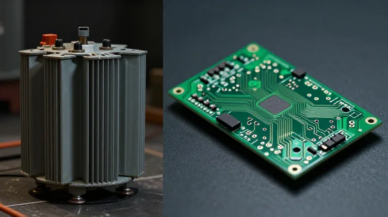
The Transition from Legacy Transformers to Modern Power Modules
For decades, dental diagnostic equipment relied on heavy, inefficient high-voltage transformers and large capacitor banks to power X-ray sources. These legacy systems, while robust, were constrained by low-frequency switching, resulting in high heat generation, significant weight, and less consistent X-ray output. The diagnostic power landscape has been fundamentally altered by the advent of solid-state electronics and high-density Printed Circuit Board (PCB) designs.
Modern power delivery in dental imaging prioritizes high-frequency switching and localized power regulation. By moving from centralized, cabinet-based power conversion to modular, PCB-integrated solutions, manufacturers have achieved significant improvements in stability and patient safety.
| Feature | Legacy High-Voltage Systems | Emerging PCB-Integrated Solutions |
|---|---|---|
| Switching Frequency | Low (50/60 Hz) | High (100 kHz+) |
| Component Density | Low (Large Transformers) | High (SMD Components) |
| Radiation Output | Variable/Pulsed | Precise/Constant Potential |
| System Weight | Heavy/Stationary | Lightweight/Modular |
Key Advantages of Modern Power Integration
- Enhanced Diagnostic Precision
Modern PCB power supplies offer near-constant potential (DC) output, significantly reducing soft-radiation artifacts and providing sharper image contrast for early pathology detection. - Reduced Radiation Exposure
Advanced circuitry allows for rapid on-off switching of the X-ray tube, minimizing the 'tail' of radiation during initialization and ensuring patients receive only the necessary diagnostic dose. - Thermal Management
High-frequency switching reduces energy loss, allowing for smaller, more efficient systems that operate with lower thermal footprints without requiring massive heat sinks.
Limitations of Legacy High-Voltage Power Architectures
The Thermal and Volumetric Bottleneck
Traditional high-voltage generators for dental X-ray units have long relied on oil-filled transformer assemblies and discrete silicon-controlled rectifiers. While these systems provided the necessary kilovoltage for decades, they suffer from inherent physical constraints. Large electromagnetic transformers generate significant parasitic heat, necessitating massive heat sinks and cooling structures that limit the miniaturization of X-ray heads. Furthermore, the reliance on bulk capacitors for voltage stabilization introduces latency in pulse modulation, which restricts the precision of short-exposure imaging required for modern, low-dose clinical protocols.
Comparison of Power Architectures
| Metric | Legacy Transformer Systems | Modern PCB-Integrated Solutions |
|---|---|---|
| Component Volume | High (Bulky Oil/Core) | Low (Integrated SMT) |
| Heat Management | Passive/Convection Limited | Active PCB Thermal Vias |
| Switching Speed | Low (kHz Range) | High (MHz Range) |
| Reliability | Prone to Oil Leakage/Arcing | Solid-state robustness |
Frequently Asked Questions
- Why is heat dissipation a limiting factor in legacy designs?
Legacy transformers dissipate energy as heat through copper and core losses; because these components are bulky and often encased in non-conductive dielectric oil, they act as thermal insulators rather than conduits, slowing down the imaging cycle. - How does physical bulk impact clinical ergonomics?
Increased weight at the distal end of the dental X-ray arm leads to mechanical drift and fatigue, making it difficult for technicians to position the sensor precisely for optimal imaging, which directly impacts diagnostic accuracy. - Are there safety implications to traditional high-voltage architectures?
Yes, aging transformers and capacitor banks are prone to dielectric breakdown and oil contamination, which can lead to equipment failure or potential safety risks in sensitive clinical environments.
The Rise of High-Frequency Power Electronics

The Shift to High-Frequency Conversion
The transition from low-frequency, line-powered transformers to high-frequency switched-mode power supplies (SMPS) represents the most significant architectural advancement in dental radiography. By operating at frequencies in the range of 50 kHz to 200 kHz, modern systems minimize the physical footprint of magnetic components. This shift allows for the integration of smaller, lightweight capacitors and inductors that drastically reduce the overall volume of the generator, facilitating the development of handheld or compact wall-mounted intraoral imaging units.
Operational Impact on Imaging Performance
Beyond miniaturization, high-frequency conversion yields cleaner DC output profiles. This stability is critical for the X-ray tube to maintain a constant focal spot, which directly minimizes motion blur and enhances image sharpness. Furthermore, the rapid response time of modern power electronics allows for precise dose control, ensuring patients are exposed only to the necessary radiation level, thereby upholding the ALARA (As Low As Reasonably Achievable) principle.
| Feature | Legacy Systems | High-Frequency Systems |
|---|---|---|
| Switching Frequency | 50-60 Hz | 50 kHz - 200 kHz |
| Transformer Size | Large, Iron-Core | Miniature, Ferrite-Core |
| Dose Accuracy | Low/Variable | High/Precise |
| Heat Dissipation | High/Inefficient | Optimized/Low Loss |
Frequently Asked Questions
- How does high-frequency power improve patient safety?
Higher frequencies allow for near-instantaneous control of the X-ray pulse, eliminating the 'soft' radiation inherent in slow-starting legacy units that contributes to unnecessary patient exposure. - Why are ferrite-core transformers preferred?
Ferrite materials exhibit significantly lower core losses at higher frequencies, enabling substantial downsizing of the transformer without sacrificing power density or thermal performance. - Does this technology impact the lifespan of the X-ray tube?
Yes; by providing a highly stable voltage ripple, high-frequency systems reduce thermal stress on the tube cathode and anode, effectively extending the operational lifecycle of the X-ray source.
Harnessing HDI Technology for Precision Imaging
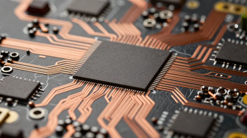
The Shift to HDI Architecture
High-Density Interconnect (HDI) technology marks a significant departure from standard multi-layer PCBs, utilizing laser-drilled microvias and finer lines to significantly boost component density. In the context of dental imaging, this allows engineers to pack sophisticated sensor control circuits and high-voltage drivers into a footprint that was previously unattainable. By reducing the physical distance between critical signal paths, HDI minimizes inductance and electromagnetic interference (EMI), which are frequent culprits of noise in low-voltage diagnostic sensor readings.
Signal Integrity and Miniaturization
In dental radiology, signal fidelity is paramount. Legacy PCB layouts often suffered from parasitic capacitance caused by long trace runs required to manage high-voltage components. HDI architectures mitigate this by allowing for 'any-layer' via connectivity, which facilitates shorter return paths and improved grounding schemes. This superior layout flexibility ensures that high-speed data from sensors is processed with minimal distortion, leading to higher contrast and resolution in the final diagnostic image.
| Feature | Legacy Multilayer PCB | HDI Technology |
|---|---|---|
| Via Structure | Through-hole (mechanical) | Microvias (laser-drilled) |
| Signal Interference | Higher (longer traces) | Lower (optimized short-path) |
| Component Density | Low/Moderate | Very High |
| Size Optimization | Bulky footprint | Ultra-compact |
Frequently Asked Questions
- How does HDI improve dental X-ray image quality?
By shortening electrical pathways and improving grounding, HDI reduces high-frequency noise and parasitic signal degradation, resulting in sharper and clearer diagnostic output. - Does HDI technology increase manufacturing costs?
While unit fabrication costs for HDI boards are higher due to laser drilling and tighter tolerances, the overall system cost is often reduced by decreasing the size of the imaging head housing and streamlining assembly. - Can HDI survive the high-voltage requirements of dental imaging?
Yes, provided the stack-up design is correctly managed for isolation distances. HDI allows for more precise isolation barriers, often providing better thermal management than traditional crowded layouts.
Design Challenges: Balancing Thermal Management and Density
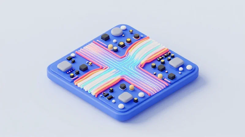
The Engineering Paradox: Density vs. Dissipation
As dental practitioners demand smaller, more ergonomic handsets, engineers are forced to pack high-frequency power electronics into increasingly confined volumes. This miniaturization creates a significant design challenge: while High-Density Interconnect (HDI) PCBs enable smaller footprints, they also concentrate heat sources, threatening component longevity and signal integrity. Balancing these factors requires a move away from passive cooling strategies toward integrated, active thermal management.
Comparison of Cooling Strategies
| Strategy | Density Capacity | Thermal Efficiency | System Complexity |
|---|---|---|---|
| Passive Heat Spreading | Low | Moderate | Low |
| Active Forced Air | Moderate | High | Moderate |
| Integrated Liquid Cooling | High | Very High | High |
Mitigation Through Advanced PCB Materials
To maintain high power densities without sacrificing performance, developers are increasingly leveraging thermally conductive PCB substrates. Metal-core PCBs (MCPCBs) and advanced ceramic-filled laminates act as high-efficiency heat spreaders, effectively drawing thermal energy away from sensitive X-ray power components and into the structural chassis of the device.
Frequently Asked Questions
- Why does increased density affect signal integrity?
Higher density leads to closer proximity of traces and components, increasing the risk of crosstalk and electromagnetic interference (EMI), which can degrade the precision of dental imaging outputs. - How do modern PCBs assist with thermal management?
Modern designs use blind and buried vias to conduct heat from surface components directly into inner ground planes, which act as a massive, unified heat sink for the entire system. - Is liquid cooling viable for hand-held dental devices?
While traditional liquid cooling is bulky, micro-fluidic cooling paths integrated into the PCB structure itself are an emerging solution for extreme power density requirements in clinical imaging equipment.
Impact on Clinical Workflow and Patient Experience
Transforming the Clinical Environment
The transition from bulky, legacy high-voltage power supplies to streamlined, PCB-integrated high-frequency systems fundamentally alters the dental operatory. By minimizing the physical footprint of imaging hardware, practitioners gain ergonomic flexibility and improved maneuverability. This integration allows for more precise sensor placement and reduced procedural times, directly enhancing the workflow and comfort of both the dentist and the patient.
Comparative Impact: Legacy vs. Emerging Technologies
| Feature | Legacy HV Systems | Emerging PCB Solutions |
|---|---|---|
| Device Weight | High (Bulky) | Low (Lightweight) |
| Radiation Output | Variable/Higher | Precise/Lower |
| Image Quality | Standard | High-Resolution |
| Clinical Workflow | Cumbersome | Seamless |
Patient-Centric Benefits: Safety and Speed
Beyond physical design, the primary impact on the patient lies in reduced radiation dosage. Advanced power electronics enable tighter control over exposure settings and pulse frequency, ensuring that the necessary diagnostic clarity is achieved with minimal ionization. Faster image processing speeds also reduce the time a patient must remain still, decreasing the incidence of motion artifacts and the need for repeated imaging procedures.
Frequently Asked Questions
- How does PCB integration reduce radiation?
Modern high-frequency power electronics allow for shorter, more precise X-ray pulses, which reduces the total radiation exposure per image without sacrificing diagnostic quality. - Will smaller hardware mean shorter lifespan?
No; while components are denser, high-density interconnect (HDI) PCBs are specifically engineered for improved thermal management and durability in compact spaces. - How do these changes affect chairside communication?
With faster imaging and portable, ergonomic handsets, dentists can spend less time adjusting hardware and more time reviewing real-time images with patients to improve treatment acceptance.
Future Outlook: The Integration of Smart Imaging
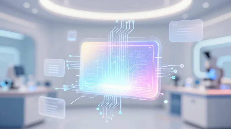
The Convergence of AI and Embedded Imaging Systems
As the industry shifts away from passive high-voltage legacy systems, the future of dental imaging lies in smart imaging hardware. Future PCB architectures are evolving into 'intelligent substrates' that integrate local processing power directly within the imaging sensor. By offloading initial data processing to edge-computing chips mounted directly on high-speed PCBs, manufacturers can drastically reduce latency and enable real-time image enhancement before data even reaches the workstation.
Anticipated Technological Transitions
| Feature | Legacy Systems | Smart Integrated Systems |
|---|---|---|
| Connectivity | Hard-wired/Analog | IoT-Enabled/Wireless |
| Data Processing | Centralized/Workstation | Edge/On-Sensor |
| PCB Architecture | Standard Multi-layer | HDI/Flexible Hybrid |
Strategic Implementation of IoT in Dentistry
Integrating IoT protocols into dental imaging hardware requires a shift toward low-power, high-signal integrity PCB designs. Future systems will leverage miniaturized antennas and low-power Wi-Fi modules integrated directly onto the sensor assembly, eliminating bulky cabling while maintaining the stringent safety standards required for patient-facing electronics.
Frequently Asked Questions
- How will smart imaging impact equipment lifespan?
Predictive maintenance algorithms enabled by smart sensors can monitor PCB voltage stability, flagging potential hardware failures before they result in system downtime. - Does smart imaging introduce cybersecurity risks?
As devices become connected, manufacturers are adopting hardware-level encryption on PCB components to ensure that patient diagnostic data remains secure during transmission.
The shift toward HDI and high-frequency power systems is not just an incremental improvement—it is the foundation of modern digital dentistry. By optimizing your hardware infrastructure today, you secure your position as a leader in diagnostic precision. Contact our engineering team to discuss how your next imaging project can leverage these advanced power solutions.
