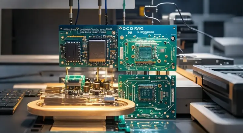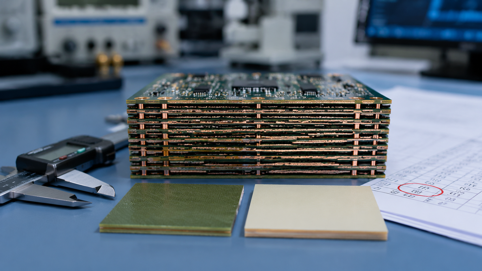
In the PCB industry, an increasingly clear trend has emerged: when layer counts exceed 12, 18, or even 24 layers, and signal rates cross the 3GHz, 5GHz, or 10GHz threshold, low-loss materials have become a mandatory consideration in design reviews — not a nice-to-have.
Many designers new to high-speed, high-layer-count boards ask: "I've used FR-4 for ten years. Why do I need to change materials now?"
The answer is not that FR-4 has gotten worse. It's that the laws of physics, under the combined pressures of high frequency, high density, and long transmission paths, no longer leave enough margin for general-purpose materials.
To understand material selection, we first need to clarify what "loss" really means in PCB engineering. We focus on two types of loss: conductor loss and dielectric loss.
Conductor loss depends on copper foil roughness and the skin effect. At high frequencies, skin depth decreases sharply, the effective conductive cross-section narrows, resistance increases, and signal energy is converted to heat. This is an unavoidable physical cost of high-frequency signals.
Dielectric loss is what truly troubles high-layer-count PCB designers — it originates from dipole polarization relaxation in the insulating dielectric (glass fiber and resin) under alternating electric fields. During each cycle, a portion of electrical energy is absorbed and dissipated by the dielectric, measured as the loss tangent (tanδ).
| Material Type | Typical tanδ (below 1GHz) | Relative Cost |
|---|---|---|
| FR-4 | 0.02 – 0.025 | Baseline |
| Low-Loss Materials (e.g., MEGTRON 6, TU-862, R-5775K) | 0.005 – 0.008 | 2 – 4× |
The difference is 3–5× — which is why FR-4 stops being sufficient once data rates go up.
Some designers argue: "My trace length is only a few centimeters — how much loss can there be?"
But high-layer-count boards often function as backplanes, switches, or server motherboards, where a single differential pair can span 200mm or 300mm, passing through multiple vias, connectors, and layer transitions. On these long links, dielectric loss increases linearly with frequency, while conductor loss increases with the square root of frequency.
Real-world data:
At 56Gbps PAM4, the Nyquist frequency is approximately 14GHz
Microstrip insertion loss at this frequency: 0.8 – 1.2dB/inch
With FR-4, a 30-inch backplane easily exceeds 15dB total loss
What does 15dB mean? The eye opening at the receiver is essentially zero. The role of low-loss materials is not to eliminate loss, but to reduce per-inch loss to 0.4 – 0.6dB/inch, keeping total link loss within the compensation range of equalizers and CDR (Clock Data Recovery) — this is the engineering lifeline.
Material selection goes far beyond a single loss tangent data sheet. The unique challenge of high-layer-count boards — many layers, multiple lamination cycles, uneven copper distribution — demands attention to glass transition temperature (Tg), thermal decomposition temperature (Td), and Z-axis coefficient of thermal expansion (CTE).
Low-loss materials are expensive because while reducing polar groups (such as hydroxyl and ester groups), they must also maintain sufficient crosslink density and heat resistance. For example, modified polyphenylene ether (PPE) or hydrocarbon resin systems can reduce tanδ while raising Tg to 180°C – 200°C and Td above 350°C, enabling them to withstand multiple reflow cycles.
Conversely, some early low-loss materials had excellent electrical performance but high moisture absorption, causing significant Dk drift in humid environments and impedance失控. These are not uncommon lessons in 20+ layer military or communication boards.
Another often-overlooked dimension is the glass weave effect. High-speed signals propagating through regions with different glass fiber density experience local Dk variations, causing mode conversion and phase jitter — manifesting as increased deterministic jitter.
Leading low-loss material suppliers now offer open-weave or flattened glass fabric, combined with resin-fill optimization, to make the dielectric constant more uniform at the microscopic level. This is especially important for high-layer-count boards, where inner-layer traces have large reference plane spacing, and small dielectric non-uniformities are amplified along the transmission line, ultimately closing the eye diagram.
Real-world case: In a 25Gbps backplane project, switching to a low-loss material with flattened glass fabric — with no routing changes — improved eye height by 22% and reduced bit error rate from 1e-5 to 1e-14. Material margin sometimes delivers more immediate results than adjusting length-matching constraints.
The consistency contribution of low-loss materials to high-layer-count boards is often underestimated. During multi-stage lamination, resin flow and fill uniformity across different layers directly affect the effective dielectric constant.
Low-loss materials typically have more stable rheological properties, with flatter Dk-T and Dk-f curves (the rate of change of dielectric constant with frequency and temperature). This means batch production can tighten impedance deviation from ±10% to ±5%.
For backplanes requiring strict 100Ω differential impedance matching, this is the key lever to improve yield from 60% to 85%.
Low-loss materials are not a panacea. They are expensive (typically 2–4× FR-4), more sensitive to drilling burrs, plasma desmear, and lamination parameters during processing, and some grades are brittle with weaker CAF (Conductive Anodic Filament) resistance.
Therefore, the correct strategy for high-layer-count material selection is to make a comprehensive trade-off based on maximum signal rate, longest trace length, operating temperature range, and production process capability:
| Decision Factor | When to Choose Low-Loss | When FR-4 May Suffice |
|---|---|---|
| Signal Rate | ≥10Gbps per lane | Low-speed control signals |
| Trace Length | Long links (>200mm) | Short interconnects |
| Layer Count | High layer count (≥12 layers) | Low-to-mid layer count |
| Temperature Range | Wide operating range | Ambient conditions |
| Process Sensitivity | Acceptable higher processing demands | Cost-optimized |
Practical "Hybrid Stackup" Strategy: Use low-loss materials for high-speed signal layers, and standard FR-4 for power and low-frequency control layers — balancing cost and performance. This hybrid approach has been widely validated in 20+ layer backplanes and communication boards.
Selecting low-loss materials for high-layer-count PCBs is, on the surface, about improving transmission loss. In reality, it's about securing valuable engineering margin for signal integrity, thermal reliability, manufacturing consistency, and long-term stability.
In an electronics world where the speed race never stops, materials are no longer passive carriers — they are active variables that define system limits. Understanding their physics is worth more than memorizing a few datasheets.
Need Support with High-Layer-Count PCB Material Selection?
AnyPCBA has extensive experience with high-frequency and high-speed materials, including MEGTRON series, TU series, Rogers, PPE/hydrocarbon resin systems, and more — supporting hybrid stackups, high-layer-count backplanes, and HDI designs.
Our engineering team provides material selection evaluation and DFM reviews during the design phase, helping you find the optimal balance between cost, performance, and manufacturability.
Contact us to discuss your project →