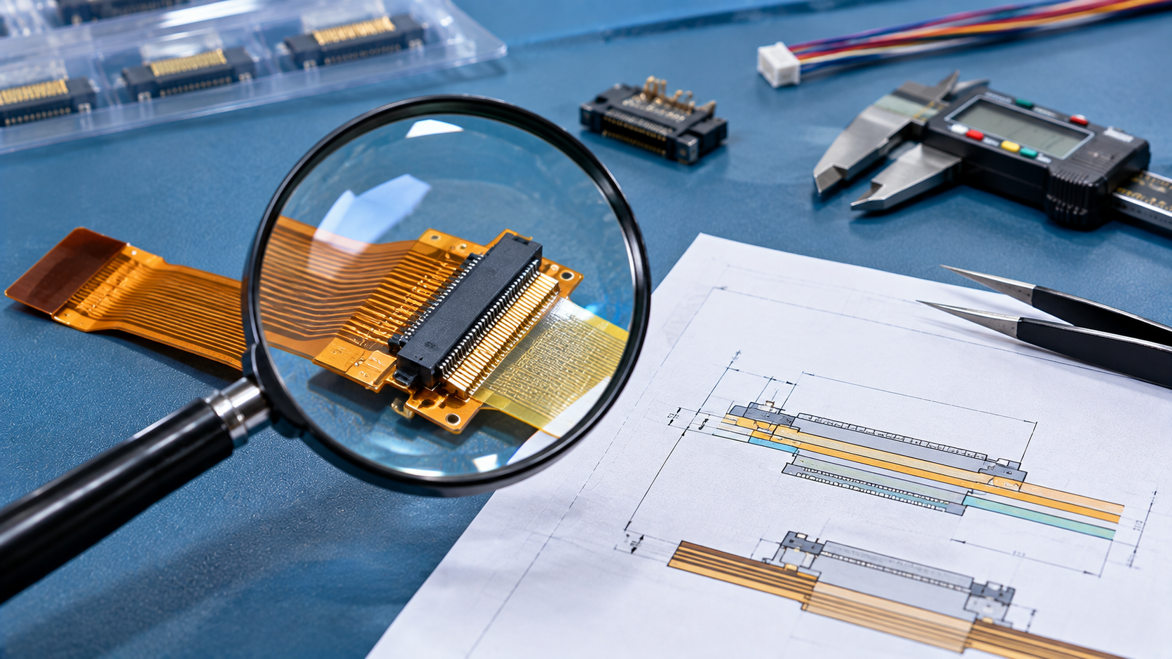
Flexible circuits have transformed the modern electronics industry, offering unmatched adaptability through their compact, lightweight designs. While they share many characteristics with rigid PCBs, flexible circuits present unique challenges and opportunities in termination. From traditional connectors to custom solutions developed specifically for flex circuits, understanding the characteristics of different termination methods is key to ensuring product durability and performance.
This guide explores termination techniques for flexible circuits, focusing on Zero Insertion Force (ZIF) connectors, unsupported flying leads, and crimp/displacement connectors. Each method has its own advantages, and the right choice depends on the specific application requirements.
Flexible circuits can accommodate various connector types, including standard through-hole/surface-mount connectors, circular/D-sub connectors, and pin header structures. These options allow designers to leverage proven design experience from rigid PCBs. However, special attention is needed: connector areas typically require stiffener support to prevent stress-induced damage.
Because connectors are heavier and more rigid than flexible substrates, conductor breakage or delamination can occur without reinforcement. Providing structural stability and evenly distributing stress through stiffeners is a critical step for ensuring long-term reliability of flexible circuits.
ZIF connectors are ideal for applications requiring frequent mating and unmating. These connectors secure the flexible circuit through a mechanical locking mechanism, achieving stable and reliable connections without excessive insertion force, while reducing wear on copper conductors.
| Advantage | Description |
|---|---|
| Durability | Minimal mechanical stress on copper traces, extending service life |
| Compact Design | No additional mating connector required, saving space and cost |
| Ease of Use | Suitable for applications requiring frequent reconnection |
Thickness Requirements: The mating area of ZIF connectors typically requires a thickness of 0.012" ± 0.002". Flexible circuits may need a polyimide stiffener in the termination area to meet specifications. To avoid stress concentration at the stiffener edge, ensure at least 0.030" overlap with the coverlay material.
Precision Control: The flexible circuit profile for ZIF connections requires extremely high precision, with tolerances up to ±0.0002". This may require advanced manufacturing processes such as laser cutting or high-precision tooling.
Surface Finish: For applications involving frequent insertion and removal, durable plating materials should be selected. Thin platings may degrade over time, exposing the underlying metal.
For applications requiring reliability, compactness, and frequent connectivity, ZIF connectors are the ideal choice.
As a highly adaptable connection solution, unsupported flying leads achieve connection through exposed conductor extensions. These "floating" conductors — not encapsulated by substrate or coverlay — can directly connect to other PCBs or components on both sides, offering flexible options for special layouts.
| Advantage | Description |
|---|---|
| Customization | Can be designed with different pitches, lengths, and layouts as needed |
| Flexibility | Electrical connection achieved without additional connectors |
| Double-Sided Access | Exposed conductor surfaces can be accessed from both sides |
Thicker Conductors for Durability: The finger area is typically designed with thicker copper conductors (typical thickness 0.010 inches), while the rest of the flexible circuit uses thinner conductors to maintain flexibility.
Laser Ablation Process: The floating characteristics of flying leads are achieved through laser ablation, which precisely removes substrate material from three sides of the conductor. This custom design meets strict specification requirements but increases overall cost.
Damage Prevention Design: Flying leads are susceptible to damage during handling and assembly. Designers often use temporary tie-bar structures for protection. These temporary connections can align and support the finger structures before final assembly is completed.
Although unsupported flying leads are more complex and costly than other methods, they offer extremely high flexibility for customized applications.
Crimp connectors provide a reliable and economical connection solution for flexible circuits. By mechanically piercing the flexible circuit, the contact wraps around the conductor to form a secure electrical and mechanical connection. These connectors are available in standard male/female configurations and can be equipped with housings for enhanced protection.
| Advantage | Description |
|---|---|
| Durability | Forms a robust connection resistant to mechanical stress |
| Cost Advantage | Practical choice for high-volume or budget-sensitive designs |
| Wide Compatibility | Standard pitches and configurations suit a broad range of applications |
Housing Options: Centerline housings can encapsulate crimp contacts, providing additional support and protection.
Customization Capability: While less customizable than unsupported flying leads, crimp connectors meet most standard application requirements (especially for size and pitch).
Application Scenarios: Suitable for applications requiring reliable connections with low assembly complexity.
Crimp connectors provide a simple and direct solution for safe, economical termination.
All termination methods require consideration of stiffeners. These structures provide mechanical support for connectors or termination areas, ensuring that weight, movement, or assembly stress does not compromise flexible circuit performance.
Select materials such as polyimide or FR-4 that are compatible with the circuit's thermal and mechanical properties
Ensure the stiffener overlaps with the coverlay material to distribute stress concentration points
Avoid affecting the natural flexibility of other circuit areas through stiffening
Regardless of the termination method, proper use of stiffeners can significantly improve the durability and reliability of flexible circuits
Flexible circuits provide innovative solutions for compact, lightweight designs, but choosing the right termination method is key to achieving performance and reliability.
Key Takeaways:
ZIF Connectors: Ideal for applications requiring high precision and frequent mating
Unsupported Flying Leads: Offer unlimited possibilities for custom layouts
Crimp Connectors: An economical and reliable choice
Stiffener Technology: Proper use significantly improves overall durability of flexible circuits
Need Flexible Circuit Design or Manufacturing Support?
AnyPCBA has extensive experience in flexible circuit (FPC) and rigid-flex design and manufacturing, supporting single-layer, double-layer, and multilayer FPC as well as rigid-flex boards for consumer electronics, automotive, medical, and other industries. Our engineering team provides DFM/DFA design reviews before production, focusing on bend area design, stiffener placement, coverlay openings, and other critical factors to help you avoid manufacturing risks from the design stage.
Contact us to discuss your project →